
Catheter tubing with improved stress-strain characteristics

a catheter and stress strain technology, applied in the field of intravascular catheter improvement, can solve the problems of limiting both trackability and time-consuming, limiting both trackability, and flexural modulus

Active Publication Date: 2007-06-12
BOSTON SCI SCIMED INC
View PDF18 Cites 24 Cited by
  • Summary
  • Abstract
  • Description
  • Claims
  • Application Information

AI Technical Summary

Benefits of technology

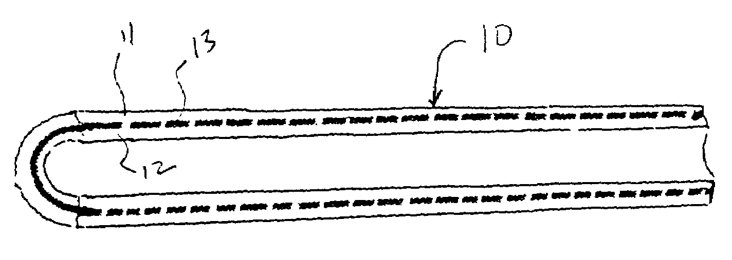
[0014]An improved medical tubing is disclosed which comprises two materials including a first material that extends between a proximal end and a distal end of the tubing and which defines a lumen. The second material extends between at least a portion of the distance between the proximal and distal ends of the tubing and is embedded in the first material. The second material is fractured.

Problems solved by technology

Advancing the catheter assembly to position the balloon across a stenosis can be a difficult and time consuming task due to the narrow and tortuous vascular passages through which the catheter assembly must be passed.
One problem associated with connecting a relatively stiff tubular member, such as a hypotube, to a more flexible tubular member, such as the catheter, is that the transition between the stiff hypotube and the more flexible catheter can result in kinking which can close the lumen of the hypotube or the lumen of the catheter thereby blocking flow through these lumens to the balloon.
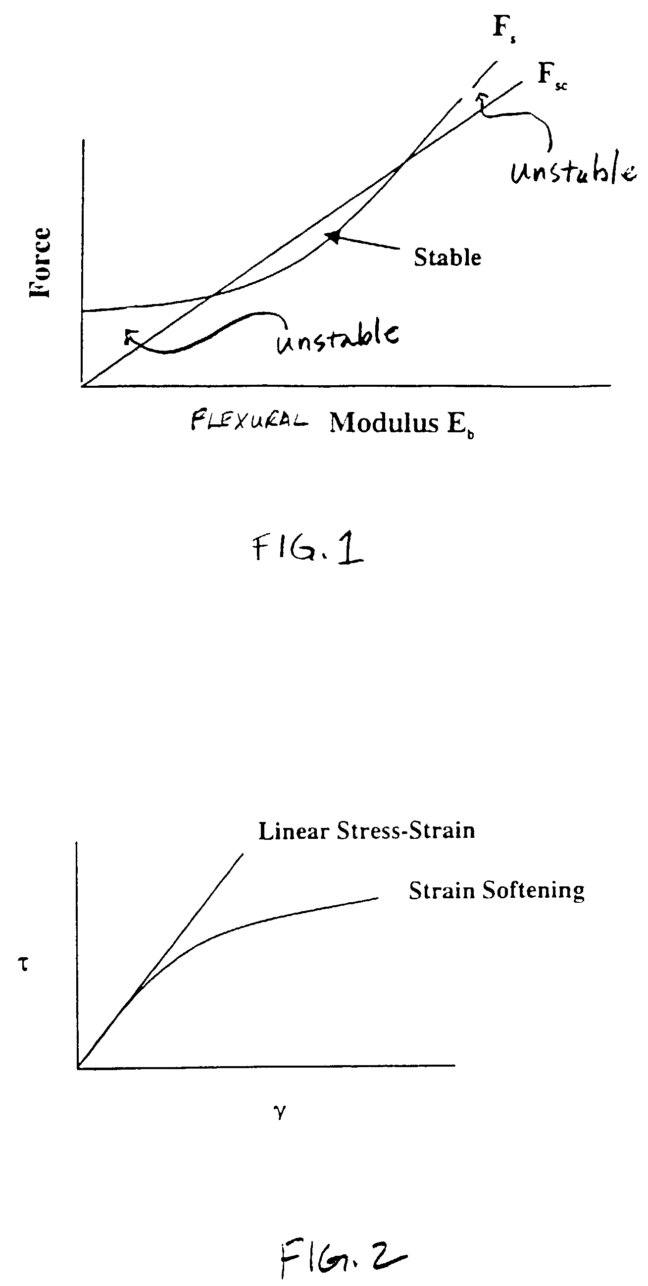
Furthermore, it is known that when the force (Fs) on a given length of tubing (1) exceeds a certain critical value (Fsc), the tubing will buckle or collapse and thus limit both the trackability, force transmission of the catheter and fluid communication through the catheter:
In addition, a high flexural modulus (Eb) can produce excessive counteractive force, producing guide catheter back-out.

Method used


Image

  • Catheter tubing with improved stress-strain characteristics
  • Catheter tubing with improved stress-strain characteristics
  • Catheter tubing with improved stress-strain characteristics

Examples


Embodiment Construction

[0030]Specifically, flexural modulus (Eb) is the ratio of stress to strain within the elastic limit. A non-linear, strain softening structure can be broadly defined as a structure wherein the stress τ exhibits a decreasing dependence on strain γ. This is illustrated in FIG. 2 wherein the “strain softening” curve of the disclosed tubing represents a tubing that takes less force (Fs) to push the tubing through a tortuous path than the linear stress-strain tubing of the prior art.

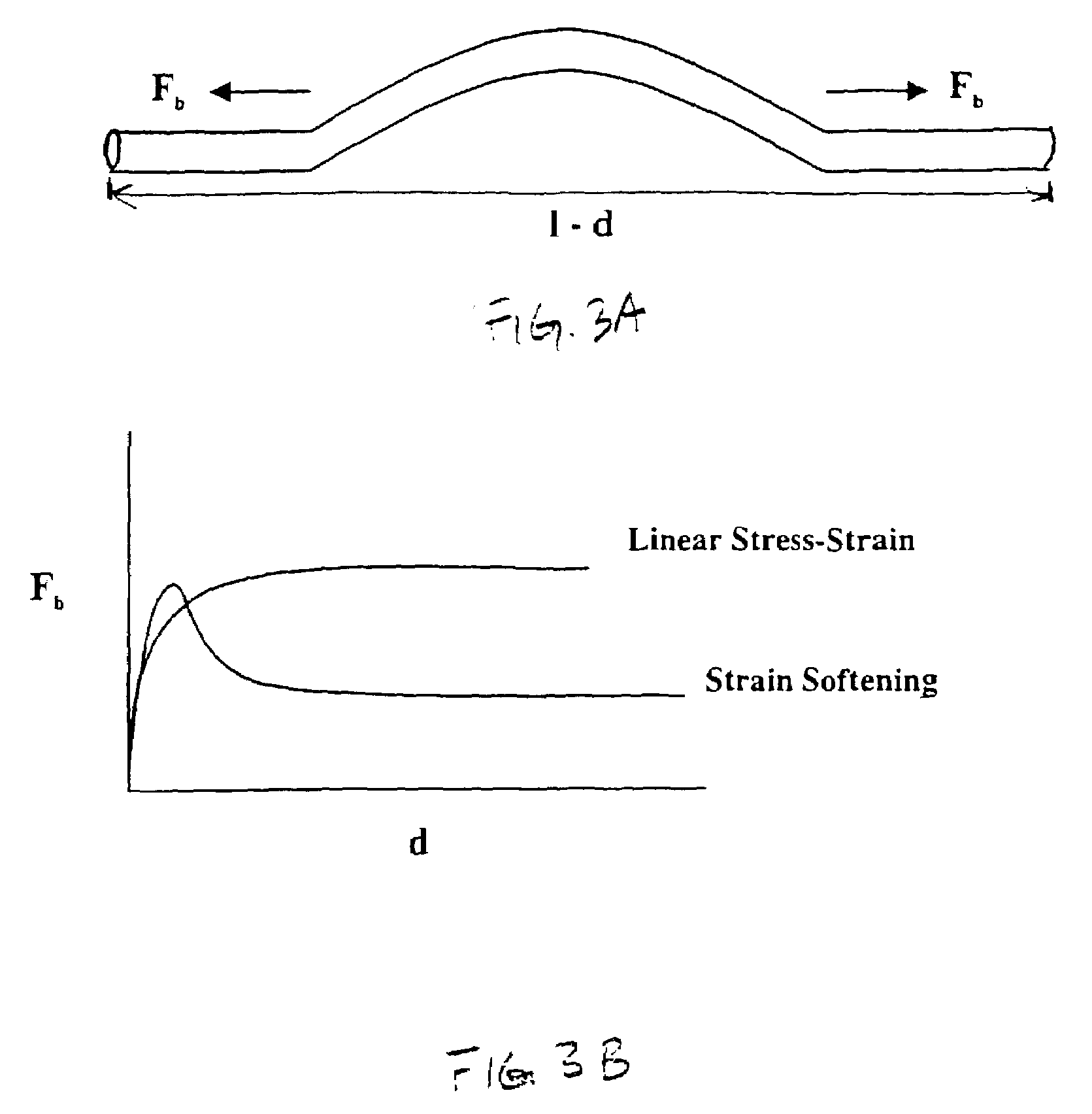
[0031]Furthermore, stress-strain properties have a large effect on the forces developed when a tubing sample traverses a tortuous path. For example, FIGS. 3A and 3B illustrate the forces that arise when a section of the tubing of length 1 undergoes a bending force Fb and is compressed or bent thereby reducing the length of the tubing by an amount d. Specifically, in FIG. 3A, the tubing of an overall length 1 has a reduced length 1-d due to the bending shown in FIG. 3A. In FIG. 3B, as d approaches zero, the str...


PUM

PropertyMeasurementUnit
flexural modulusaaaaaaaaaa
break elongationaaaaaaaaaa
flexural modulusaaaaaaaaaa

Abstract

A medical tubing is disclosed which includes a first material extending between proximal and distal ends of the tubing and which defines a lumen of the tubing. The tubing also includes a second material extending between at least portion of the distance between the proximal and distal ends of the tubing and that is embedded in the first material. The second material is fractured. The first material is flexible and the second material is relatively rigid and brittle and the two materials combined to provide a medical tubing that exhibits strain softening behavior.

Description

BACKGROUND[0001]1. Technical Field[0002]An improved intravascular catheter is disclosed. More specifically, an improved catheter is disclosed that provides improved stress-strain behavior that exhibits a sufficient degree of stiffness at low cross-axial strains for sufficient pushability, and sufficient flexibility at higher cross-axial strains for sufficient trackability.[0003]2. Description of the Related Art[0004]Intravascular catheters are widely used for a variety of diagnostic and therapeutic purposes. Specifically, angioplasty has been developed as an alternative to bypass surgery for treating vascular diseases or other conditions that occlude or reduce blood flow in a patient's vascular system. Balloon angioplasty has proven to be a useful and often a preferred treatment for coronary diseases that cause blockages, also known as stenosis, in coronary arteries as well as other parts of the vascular system.[0005]Advancing the catheter assembly to position the balloon across a s...

Claims


Application Information

Patent Timeline
Patent Type & Authority Patents(United States)
IPC IPC(8): F16L9/14A61M25/00A61L29/04A61L29/14
CPCA61L29/04A61L29/14A61M25/005Y10T428/1393A61M25/0054
Inventor CHEN, JOHN JIANHUADEVENS, JR., DOUGLAS A.MILLER, PAUL JAMESPARSONAGE, EDWARD
Owner BOSTON SCI SCIMED INC
Learn More