Hammer tacker, and tack therefor

a hammer tack and hammer technology, applied in the direction of nails, nailing tools, fastening means, etc., can solve the problems of difficult to achieve uniformity between one copy and another, difficult to keep within even a loose dimensional tolerance, and difficult to fabricate individual custom spring designs. , to achieve the effect of high efficiency, reliable and reliable operability

Inactive Publication Date: 2007-06-12
EVANS JR R V DICK +1
View PDF6 Cites 6 Cited by
  • Summary
  • Abstract
  • Description
  • Claims
  • Application Information

AI Technical Summary

Benefits of technology

[0002]The invention generally relates to a manual hammer tacker for striking a procession of inventive fasteners or tacks on a repetitive and highly efficient basis. Such tacks are characterized by, among other things, a broad flat head that is particularly effective for fastening soft, thin, membrane materials, such as vapor wraps like Tyvek®. In accordance with the present invention, the hammer tacker disclosed herein is particularly improved for more dependable and reliable operability, especially on vertical surfaces in contrast to flat or gently sloping surfaces.
[0017]It is an object of the invention to eliminate where possible custom design springs in favor of readily available, off-the-shelf parts.
[0019]It is an additional object of the invention to impose much closer dimensional tolerances on the springs because of simpler designs which are achieved by simply trimming such off-the-shelf stock to size or, in other words, eliminate overly-complicated spring designs achieved by layout on flat stock, formation into convoluted shapes, heat treatment to render the material serviceable again as a spring component, and then re-tuning the component to compensate for distortions brought on by the heat treatment.

Problems solved by technology

As such, the spring designs prove challenging to fabricate and nearly impossible to achieve uniformity between one copy to the next.
However, industry-specified heat treatments cause distortions, probably in all cases, it being usual that such distortions are readily apparent to by the un-aided eye alone.
Moreover, each individual custom spring-design is likely overly-complicated in terms of both layout and formation.
As for formation especially of the rocker-arm / pawl linkage and its supplemental spring, these involve formation of tricky bends and curves that prove challenging to keep within even a loose dimensional tolerance.
As said, dimensional tolerance laxness is only further compounded by a heat treatment that predictably adds distortion.
In consequence, it is practically impossible to produce duplicate copies of the same part.
Also, assembly is difficult. FIGS. 2 and 3 shows that the three springs 541, 544 / 545 and 546 have to be intertwined like a three-dimensional puzzle, and then carefully rested between both halves of the split housing.
If the parts as they often do get jarred apart, then a worker has to start over.
Another shortcoming is that, if during use any of these springs gets deformed through mishap, it is virtually impossible for the customer-owners of the hammer tacker to repair the hammer tacker like new because of the challenge of re-tuning the springs.
In fact, the assignee hereof has not really been any more successful at re-tuning springs deformed in the field than customer-owners.
For example, perhaps the piston will not return to its fully retracted position, and in consequence the ram's impulse surface will not clear the heads of the tacks in the strip.
Without clearance, the tack strip will not advance, the rocker-arm / pawl linkage might stay caught in a strained position.
The reason that this is ill-advised is that, it risks damaging or in other words deforming any of the delicate springs / linkages.
However, what also happens is that a substantial pre-load is built into the hammer tacker.
The piston is forced so tight against its rest stop that it requires a worker to work that much harder on each whack, a fraction of which is waste just to overcome the resting force.
Needless to say, this speeds up worker fatigue and detracts from worker efficiency.

Method used


Image

  • Hammer tacker, and tack therefor
  • Hammer tacker, and tack therefor
  • Hammer tacker, and tack therefor

Examples


Embodiment Construction

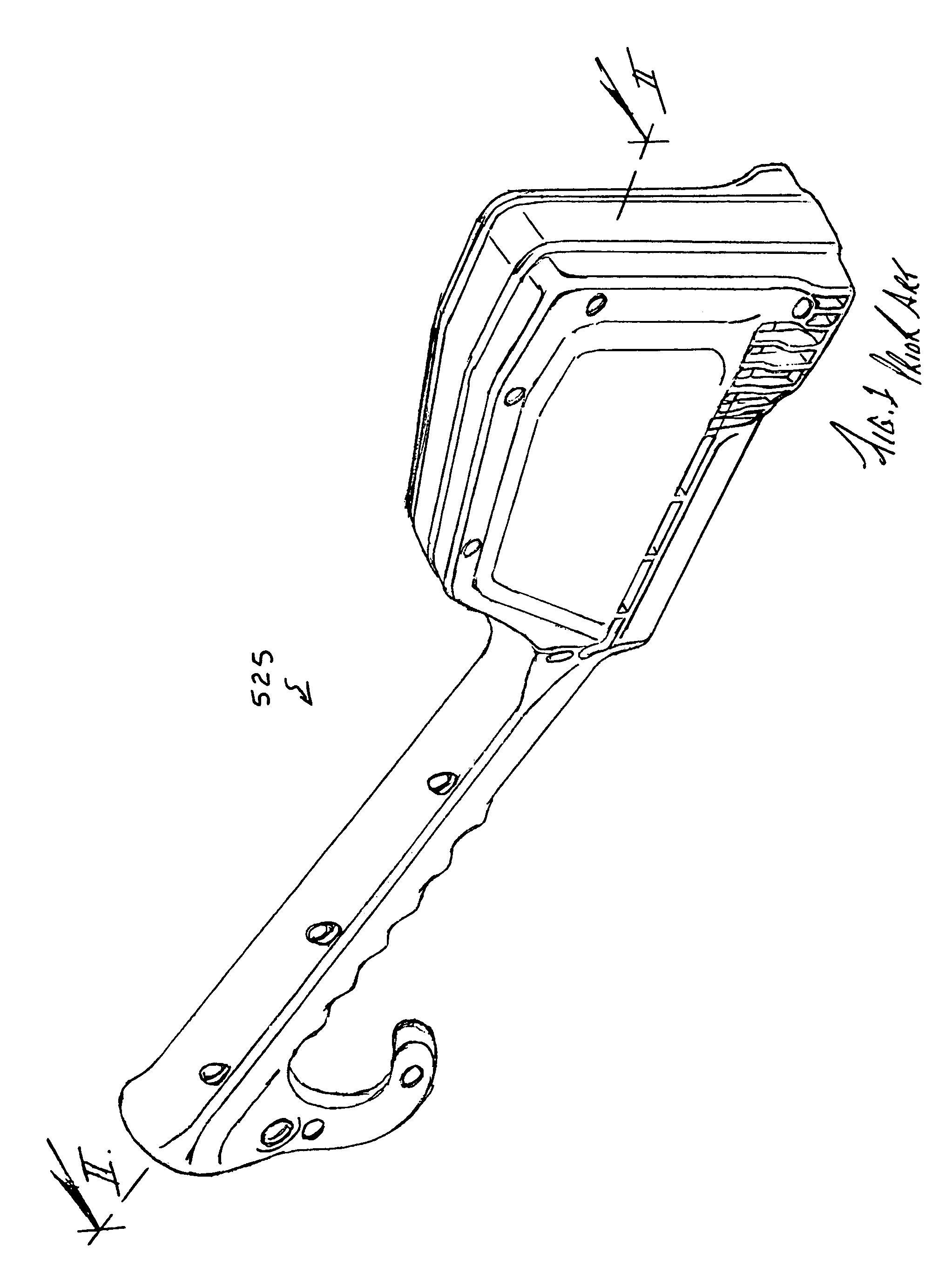
[0035]FIG. 7 shows a hammer tacker 625 in accordance with the invention.

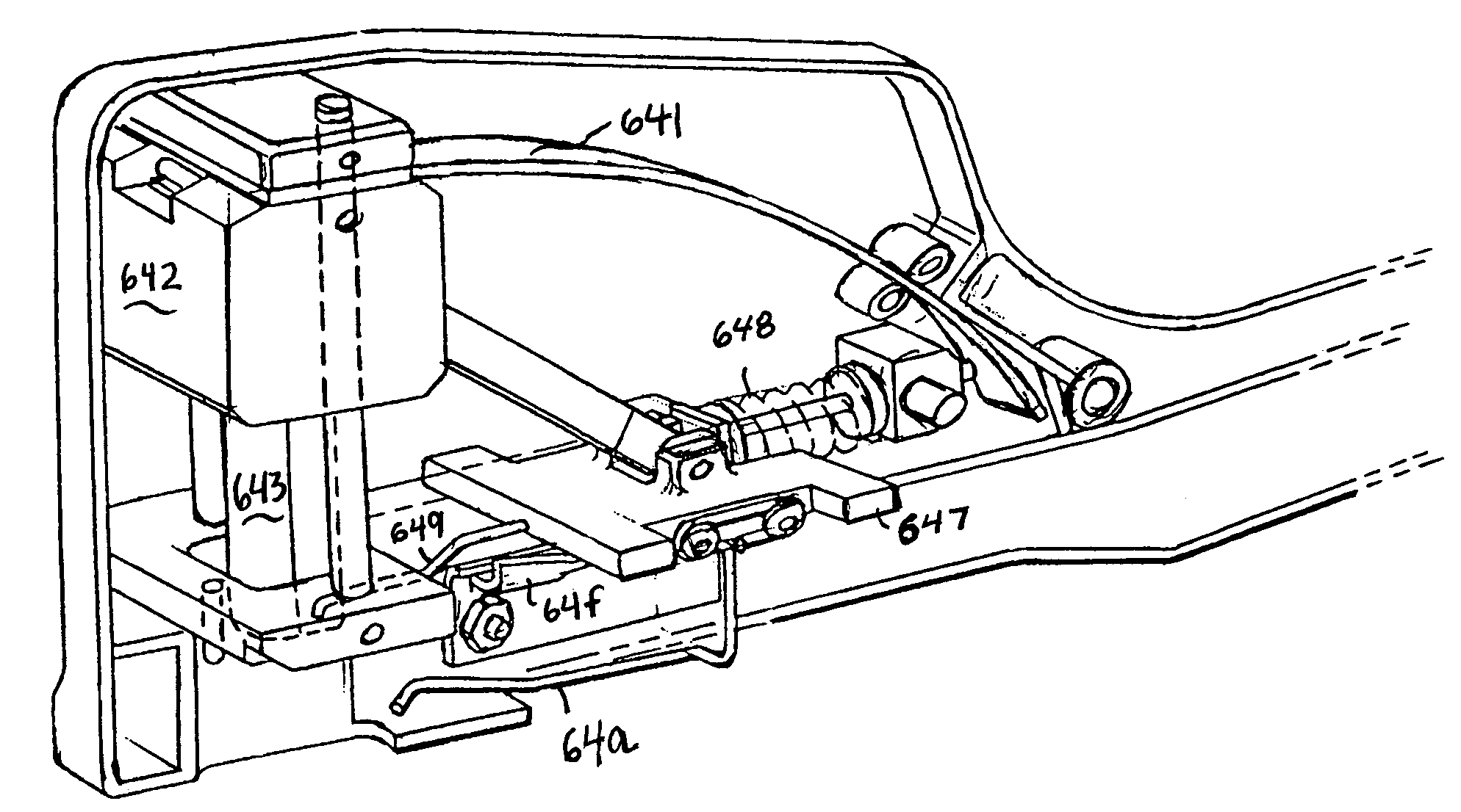
[0036]FIG. 8 is an enlarged scale perspective view taken in the direction of arrows VIII-VIII in FIG. 7, and has the near-side half of the split housing removed to better reveal the tack driving-and-feed mechanism(s). Aspects of this include the piston-and-ram unit 642 / 643, its leaf spring 641, the tack-feeding slide 647, its compression spring 648, its tack driver 649, its stabilizer 64a for the last-tack of all when proceeded to the lead position (eg., the position where the piston-and-ram unit 642 / 643 strikes it into the target).

[0037]FIG. 9 is a side elevational view of FIG. 8. The leaf spring 641 is produced from readily available off-the-shelf flat band spring steel stock. It is simply cut to length. As FIG. 9, shows, this leaf spring is simply constrained as shown without fixture to either of its ends. That is, one or both of its ends are free to slide in their constraints.

[0038]The compression spring 648...


PUM


Abstract

A hammer tacker has a strike, a tack-driving piston, a tack-feeding mechanism, and a handle for a user to cause a strike against a target. The piston cycles between drive and retraction strokes. The tack-feeding mechanism cycles between recession and feed strokes to feed the tack in a next-to-lead position to the lead position after the preceding tack in the lead position is struck into the target, and includes an escaping driver for engaging a pallet of the tack in the next-to-lead position during the feed stroke to feed that tack to the lead position, as well as for escaping the pallet of that tack during the recession stroke and then receding to engage the pallet of the tack that succeeds to the next-to-lead position, if any. Wherein as the piston's drive stroke coincides with the recession stroke, the feed stroke lags after a pause behind the piston's retraction stroke.

Description

CROSS-REFERENCE TO RELATED APPLICATION(S)[0001]This application is a continuation of U.S. patent application Ser. No. 10 / 888,528, filed Jul. 8, 2004 now abandoned, which claims the benefit of U.S. Provisional Application No. 60 / 485,533, filed Jul. 8, 2003, all of which disclosures are incorporated herein by reference.BACKGROUND AND SUMMARY OF THE INVENTION[0002]The invention generally relates to a manual hammer tacker for striking a procession of inventive fasteners or tacks on a repetitive and highly efficient basis. Such tacks are characterized by, among other things, a broad flat head that is particularly effective for fastening soft, thin, membrane materials, such as vapor wraps like Tyvek®. In accordance with the present invention, the hammer tacker disclosed herein is particularly improved for more dependable and reliable operability, especially on vertical surfaces in contrast to flat or gently sloping surfaces.[0003]The hammer tacker in accordance with the present invention ...

Claims


Application Information

Patent Timeline
Patent Type & Authority Patents(United States)
IPC IPC(8): B25C5/10B25C5/16F16B15/02F16B15/08
CPCB25C5/11F16B15/08
Inventor SCHULZ, JACK A.HAMMOND, SAM DSCHIEN, KENT F.
Owner EVANS JR R V DICK
Why Eureka
Try Eureka