Camper slide-out system

a slide-out and camper technology, applied in vehicle sanitation, transportation and packaging, transportation items, etc., can solve the problems of difficult disassembly and achieve the effect of sufficiently shortening the effective length of the shaft and relatively easy service of the slide-out uni

Active Publication Date: 2007-06-12
LIPPERT COMPONENTS MFG INC
View PDF14 Cites 22 Cited by
  • Summary
  • Abstract
  • Description
  • Claims
  • Application Information

AI Technical Summary

Benefits of technology

[0007]This provides a lightweight, low profile, and relatively inexpensive slide system. This system supports the room laterally by virtue of the connection between the slide plate and the base, and also does not overload the pinions since the slide plate is supported by the base and by the slide block.
[0009]This mechanism not only provides for infinite adjustment of the synchronization between the two slide units (so that both ends of the room open and close at the same time, to maintain parallelism between the inside and outside walls of the slide-out and the outside wall of the recreational vehicle, but also makes servicing the slide-out unit relatively easy. By screwing the lead screw all the way into the shaft, the effective length of the shaft can be sufficiently shortened so as to enable removal of the shaft, with consequent easy removal of the motor and removal of the other shaft possible. In prior art slide-out mechanisms, disassembly of the slide-out unit was often difficult because of the limited space available in which to work.

Problems solved by technology

In prior art slide-out mechanisms, disassembly of the slide-out unit was often difficult because of the limited space available in which to work.

Method used


Image

  • Camper slide-out system
  • Camper slide-out system
  • Camper slide-out system

Examples


Embodiment Construction

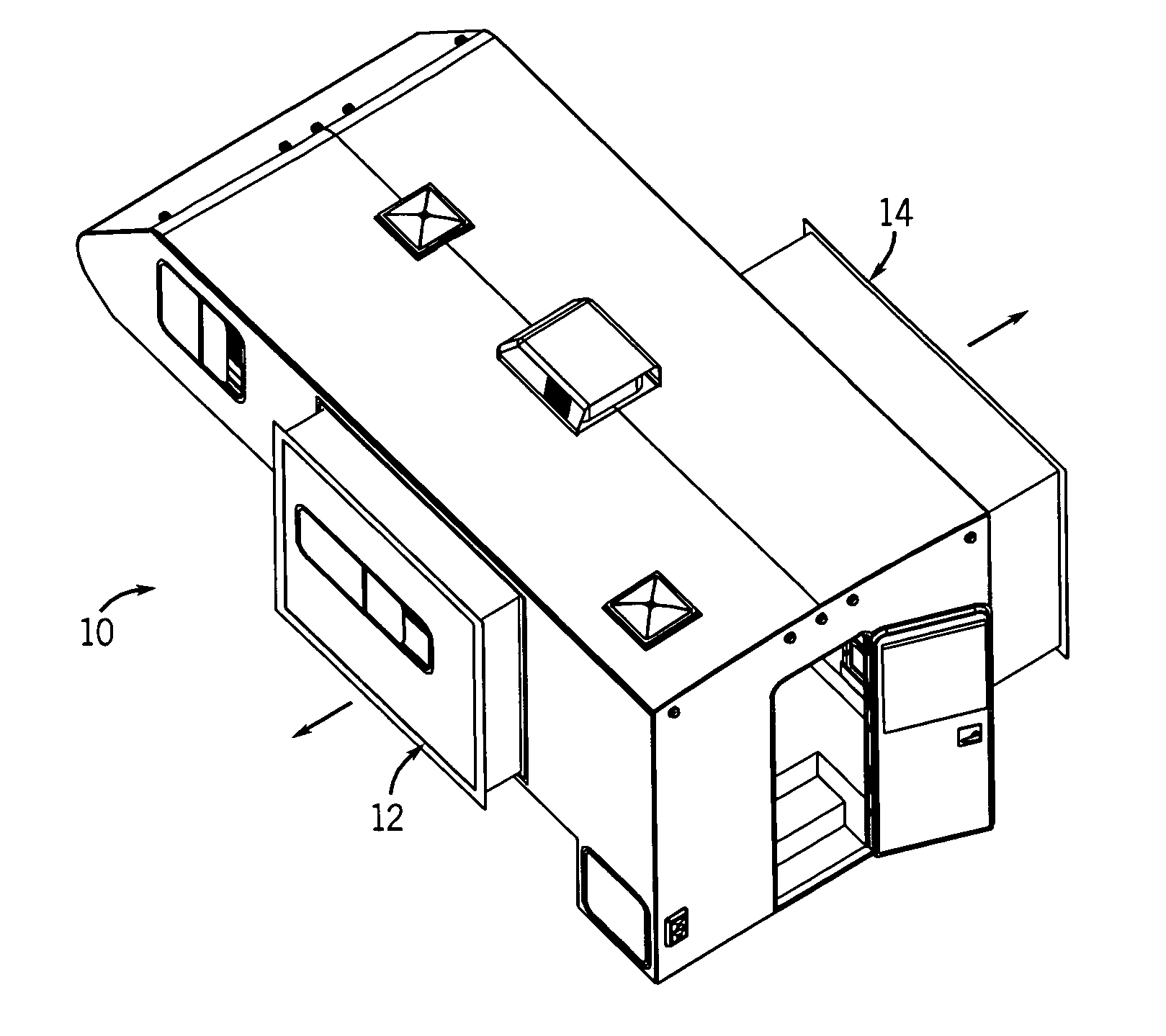
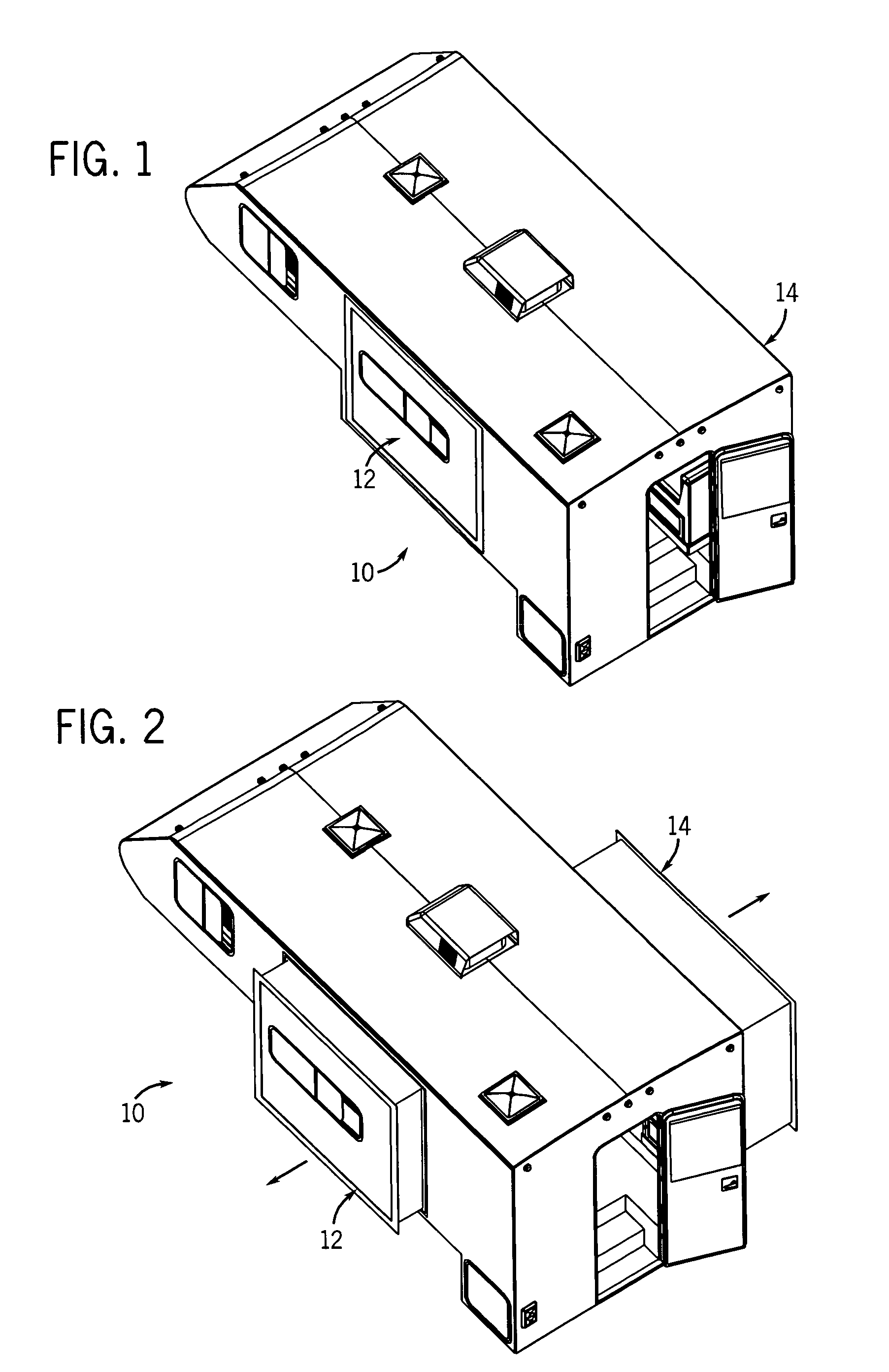
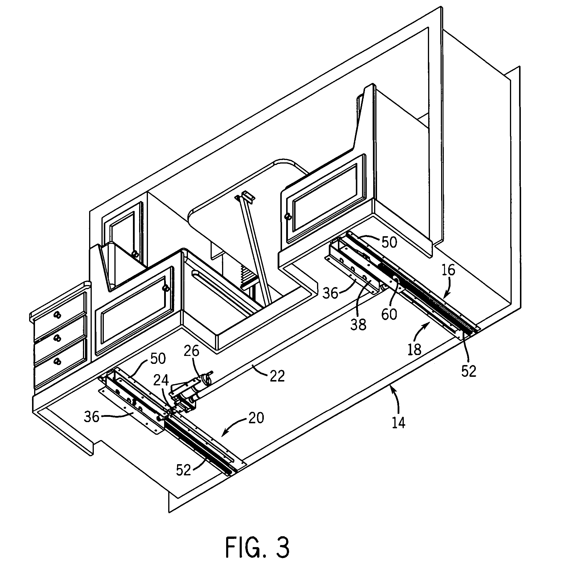
[0030]FIGS. 1 and 2 illustrate a camper 10 incorporating the invention, in this case a truck camper, for being piggybacked on a pick-up truck. FIG. 1 illustrates the camper with its slide-out rooms 12 and 14 retracted and in FIG. 2 they are extended. FIG. 3 illustrates a bottom view of the room 14, which is a dinette, with the slide-out system 16 attached to the bottom of the room. FIG. 4 illustrates the opening in the side of the camper 10 for the slide-out room 14, with the slide-out system 16 attached to the floor of the stationary room. The system 16 includes two spaced apart slide units 18 and 20, two drive shafts 22 and 24, and a motor drive unit 26. FIG. 6 illustrates the slide unit 30 on the opposite side of the camper from the unit 16, which contains similar components that may be of different sizes.

[0031]The slide units 18 and 20 are mirror-images of one another, and therefore, the description of one applies to the other. Referring to FIGS. 6 through 19, each slide unit 18...


PUM


Abstract

A slide-out system for a recreational vehicle has a slide block that is form fit with a sliding connection to a track so as to vertically and laterally support a slide-out room relative to the stationary portion of the vehicle. The room is driven in and out by a rack and pinion drive and a synchronizing screw is provided at at least one end of the drive shaft so that two spaced apart slide-out units can be synchronized relative to one another and to ease disassembly of the shafts and motor drive unit.

Description

CROSS-REFERENCE TO RELATED APPLICATION[0001]This claims the benefit of U.S. Provisional Application No. 60 / 618,040 filed Oct. 12, 2004.STATEMENT CONCERNING FEDERALLY SPONSORED RESEARCH OR DEVELOPMENT[0002]Not applicable.FIELD OF THE INVENTION[0003]This invention relates to slide-out room systems in recreational vehicles.BACKGROUND OF THE INVENTION[0004]Slide-out systems in recreational vehicles have become extremely popular. A well-known and successful slide-out system is disclosed in U.S. Pat. No. 5,758,918 which issued Jun. 2, 1998. This is a system in which two spaced apart telescoping rails support the slide-out room and are moved in and out by a rack and pinion system in which two pinion gears connected by a shaft mesh with two racks, one for each telescoping rail, and rollers are provided on opposite sides of each rack to support the rail. The pinions are powered by an electric motor operating through a gear box reduction.[0005]This type of system is well suited to a heavy-dut...

Claims


Application Information

Patent Timeline
Patent Type & Authority Patents(United States)
IPC IPC(8): B60R15/00
CPCB60P3/34
Inventor KUNZ, JAMES R.
Owner LIPPERT COMPONENTS MFG INC
Why Eureka
Try Eureka