
Ink-jet head

a technology of inkjet head and inkjet printing, which is applied in the direction of printing and inking apparatus, etc., can solve the problems of inability to perform good image recording, unstable ejection performance, and change in ink passage resistance, and achieve the effect of reducing filtration resistan

Active Publication Date: 2007-06-12
BROTHER KOGYO KK
View PDF9 Cites 12 Cited by
  • Summary
  • Abstract
  • Description
  • Claims
  • Application Information

AI Technical Summary

Benefits of technology

The present invention provides an ink-jet head with an improved design that prevents air bubbles from staying within the reservoir and clogging the nozzle. The invention includes a reservoir unit with an introduction passage, one or more discharge passages, and a filter. The filter is positioned within the introduction passage and has lower filtration resistance at its portion nearer to the inflow port, which allows ink and air bubbles to easily flow through the filter and into the lower passage. This prevents air bubbles from staying on the filter and ensures proper ink supply to the passage unit.

Problems solved by technology

However, since the filter blocks out air bubbles as well as foreign materials contained in the ink, the air bubbles stay on the filter, and growth of the air bubbles may cause a change in passage resistance of ink.
When the passage resistance changes, ink ejection performance becomes unstable and therefore good image recordings cannot be performed.
When the reservoir, even without any filter formed therein, includes a region where ink flows less smoothly, air bubbles stay within the region to cause unstable ejection performance.

Method used


Image

  • Ink-jet head
  • Ink-jet head
  • Ink-jet head

Examples


Embodiment Construction

[0027]In the following, some preferred embodiments of the present invention will be described with reference to the accompanying drawings.

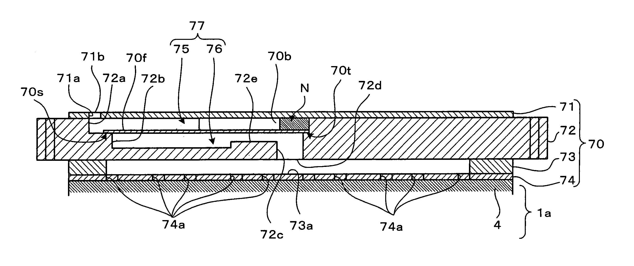
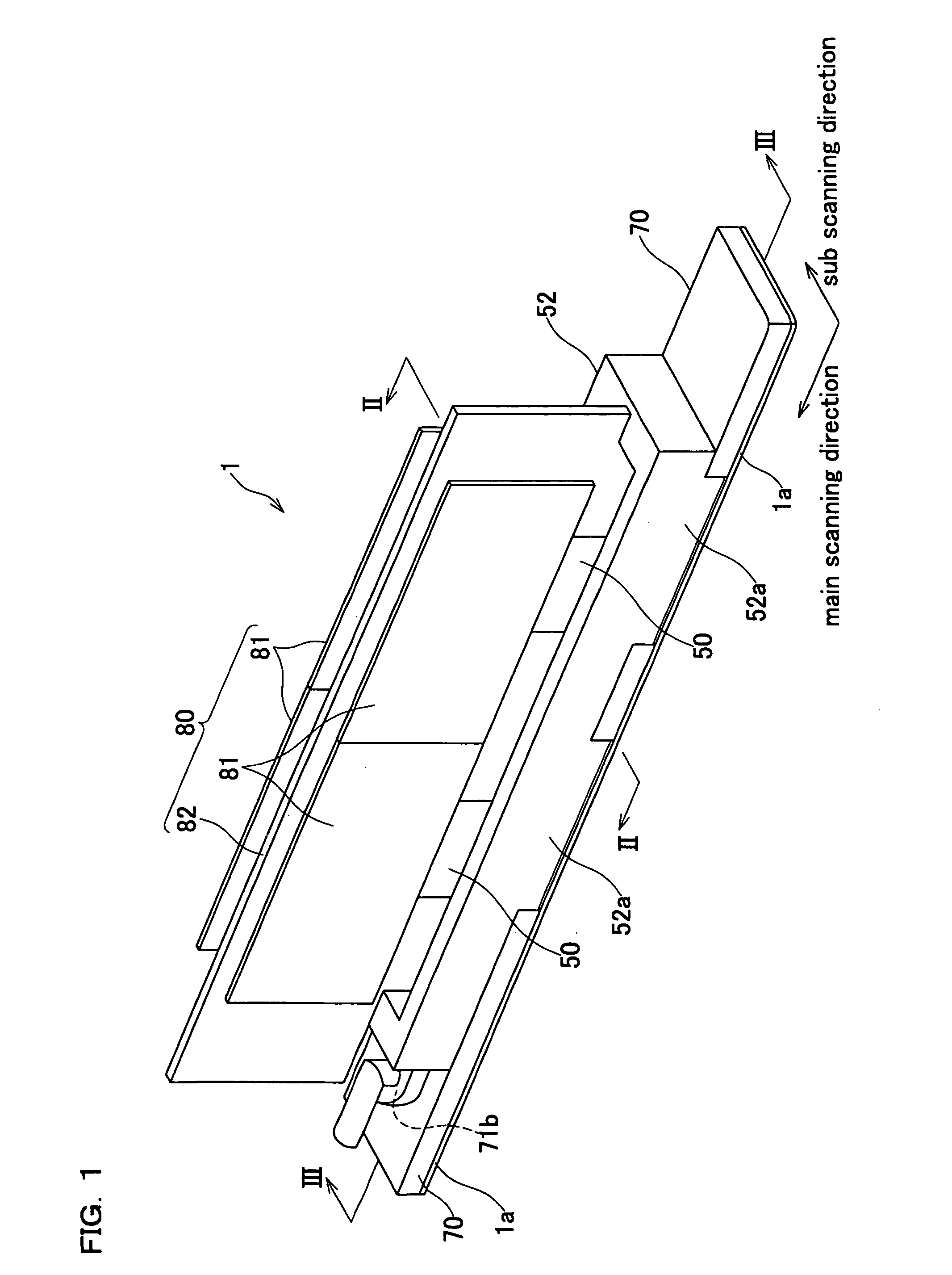
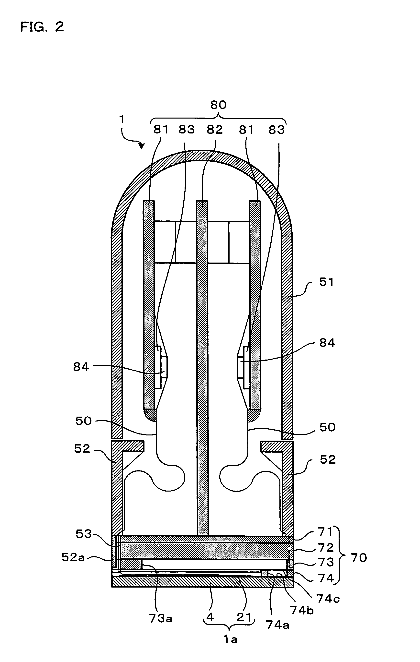
[0028]First, a description will be given to an ink-jet head according to a first embodiment of the present invention. As illustrated in FIG. 1, an ink-jet head 1 of this embodiment has a shape elongated in a main scanning direction, and comprises, from a bottom side, a head main body 1a, a reservoir unit 70 (not shown in FIG. 1; see FIG. 2), and a control unit 80 that controls driving of the head main body 1a. As illustrated in FIG. 2, an upper covering 51 and a lower covering 52 are provided for the purpose of protecting against ink an upper part of the head including the control unit 80 and a lower part thereof including the reservoir unit 70, respectively. An illustration of the upper covering 51 is omitted from FIG. 1 so that the control unit 80 may be exposed into a visible state.

[0029]Here, referring to FIGS. 1 and 2, a construction of the c...


PUM


Abstract

An ink-jet head comprises a reservoir unit that includes an ink reservoir. The reservoir unit includes an introduction passage that connects an ink introduction port and an inflow port facing the ink reservoir, and a filter that extends within the introduction passage. The introduction passage has such a configuration that, on both sides of the filter, ink can flow along the filter toward the inflow port. An ink non-passing area is formed within the reservoir unit. The ink non-passing area extends continuously, from at least a part of an area on a plane of the filter opposed to the inflow port, in a direction away from the inflow port.

Description

BACKGROUND OF THE INVENTION[0001]1. Field of the Invention[0002]The present invention relates to an ink-jet head that ejects ink onto a record medium to thereby conduct a recording.[0003]2. Description of Related Art[0004]An ink-jet head is applicable to a recording apparatus such as printers and facsimile machines, etc. The ink-jet head comprises a plurality of nozzles, pressure chambers that communicate with the respective nozzles, an actuator that selectively applies ejection energy to ink contained in the pressure chambers, and the like. Ink is supplied from an ink supply source such as an ink tank, and then distributed among the respective pressure chambers. Upon driving of the actuator, the ink is ejected from the nozzles that communicate with the pressure chambers. According to one of known techniques, this type of ink-jet head comprises, for the purpose of stable ink supply to the pressure chambers, a reservoir that stores ink having supplied from the ink supply source and s...

Claims


Application Information

Patent Timeline
Patent Type & Authority Patents(United States)
IPC IPC(8): B41J2/05B41J2/045B41J2/055B41J2/14B41J2/175
CPCB41J2/14209B41J2/17513B41J2/17563B41J2002/14217B41J2002/14225B41J2002/14419B41J2002/14459B41J2202/20
Inventor CHIKAMOTO, TADANOBUHIROTA, ATSUSHISAKAIDA, ATSUO
Owner BROTHER KOGYO KK
Learn More