
Imprint lithography template having a feature size under 250 nm

a technology of feature size and template, applied in the field of imprint lithography templates, can solve the problems of system construction, many common materials may not be optically transparent, and methods are reaching their resolution limits,

Inactive Publication Date: 2007-06-12
BOARD OF RGT THE UNIV OF TEXAS SYST
View PDF140 Cites 80 Cited by
  • Summary
  • Abstract
  • Description
  • Claims
  • Application Information

AI Technical Summary

Benefits of technology

This approach enables successful imprint lithography with precise gap control and fluid management, allowing for high-resolution feature transfer on substrates without the need for high temperatures or pressures, thereby overcoming the limitations of traditional lithography methods.

Problems solved by technology

However, it is believed that these methods are reaching their limits in resolution.
At these short wavelengths, many common materials may not be optically transparent and therefore imaging systems typically have to be constructed using complicated reflective optics.
Furthermore, obtaining a light source that has sufficient output intensity at these wavelengths may be difficult.
Such systems may lead to extremely complicated equipment and processes that may be prohibitively expensive.
It is believed that high-resolution e-beam lithography techniques, though very precise, may be too slow for high-volume commercial applications.

Method used


Image

  • Imprint lithography template having a feature size under 250 nm
  • Imprint lithography template having a feature size under 250 nm
  • Imprint lithography template having a feature size under 250 nm

Examples


second embodiment

[0107]an X-Y translation stage is depicted in FIG. 17, and generally referenced by numeral 1700. To provide a similar range of motion to that of X-Y stage 1600, stage 1700 may have a foot print of about 29 inches by 29 inches and a height of about 15 inches (including a wafer chuck). Stages 1600 and 1700 differ mainly in that additional linkages 1701 are oriented vertically.

[0108]Both X-Y stage 1600 and X-Y stage 1700 are flexure based systems. Flexures are widely used in precision machines since they may offer frictionless, particle-free and low maintenance operation. Flexures may also provide extremely high resolution. Examples of flexure based systems are disclosed in U.S. Pat. No. 4,694,703 to Routson and U.S. Pat. No. 4,062,600 to Wyse both of which are incorporated by reference as if full set forth herein. However, most flexure based systems may possess limited ranges of motion (e.g., sub mm range of motion). Embodiments disclosed herein may have a range of motion of more than...

third embodiment

[0142]In a third embodiment, overlay marks may be formed of a different material than the template. For example, a material selected to form the template overlay marks may be substantially opaque to analyzing light (e.g., visible light), but transparent to activating light used as the curing agent (e.g., UV light). For example, SiOX where X is less than 2 may form such a material. In particular, it is believed that structures formed of SiOX where X is about 1.5 may be substantially opaque to visible light, but transparent to UV light.

[0143]FIG. 32, depicts an assembly of a system, denoted generally as 100, for calibrating and orienting a template, such as template 12, about a substrate to be imprinted, such as substrate 20. System 100 may be utilized in a machine, such as a stepper, for mass fabrication of devices in a production environment using imprint lithography processes as described herein. As shown, system 100 may be mounted to a top frame 110 which may provide support for a...


PUM

PropertyMeasurementUnit
distanceaaaaaaaaaa
depthaaaaaaaaaa
wavelengthsaaaaaaaaaa

Abstract

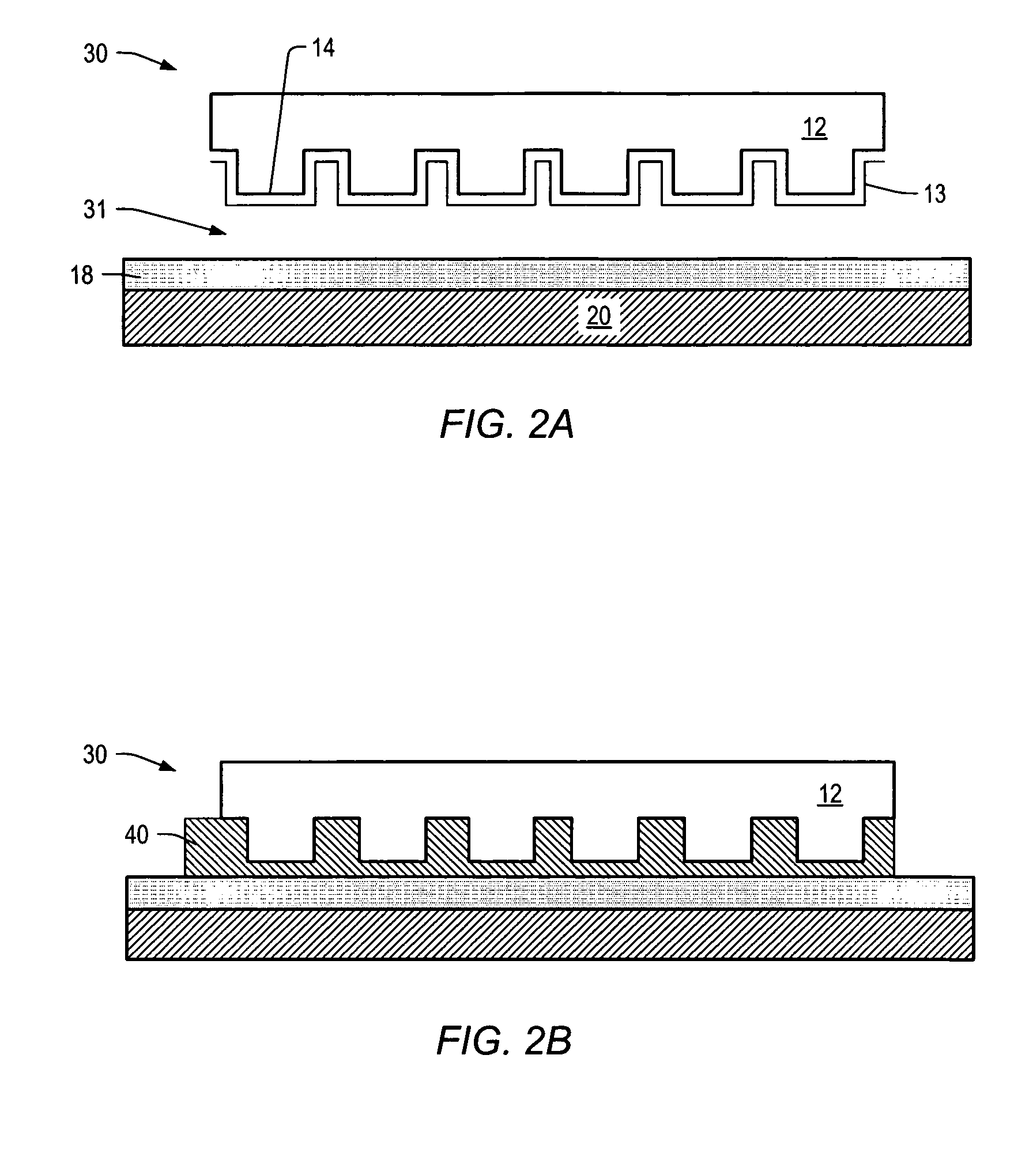
The present invention includes a template comprising a plurality of protrusions and a plurality of recessions with a distance between a zenith of any of the plurality of protrusions and a nadir of any one of the plurality of recessions being less than 250 nm.

Description

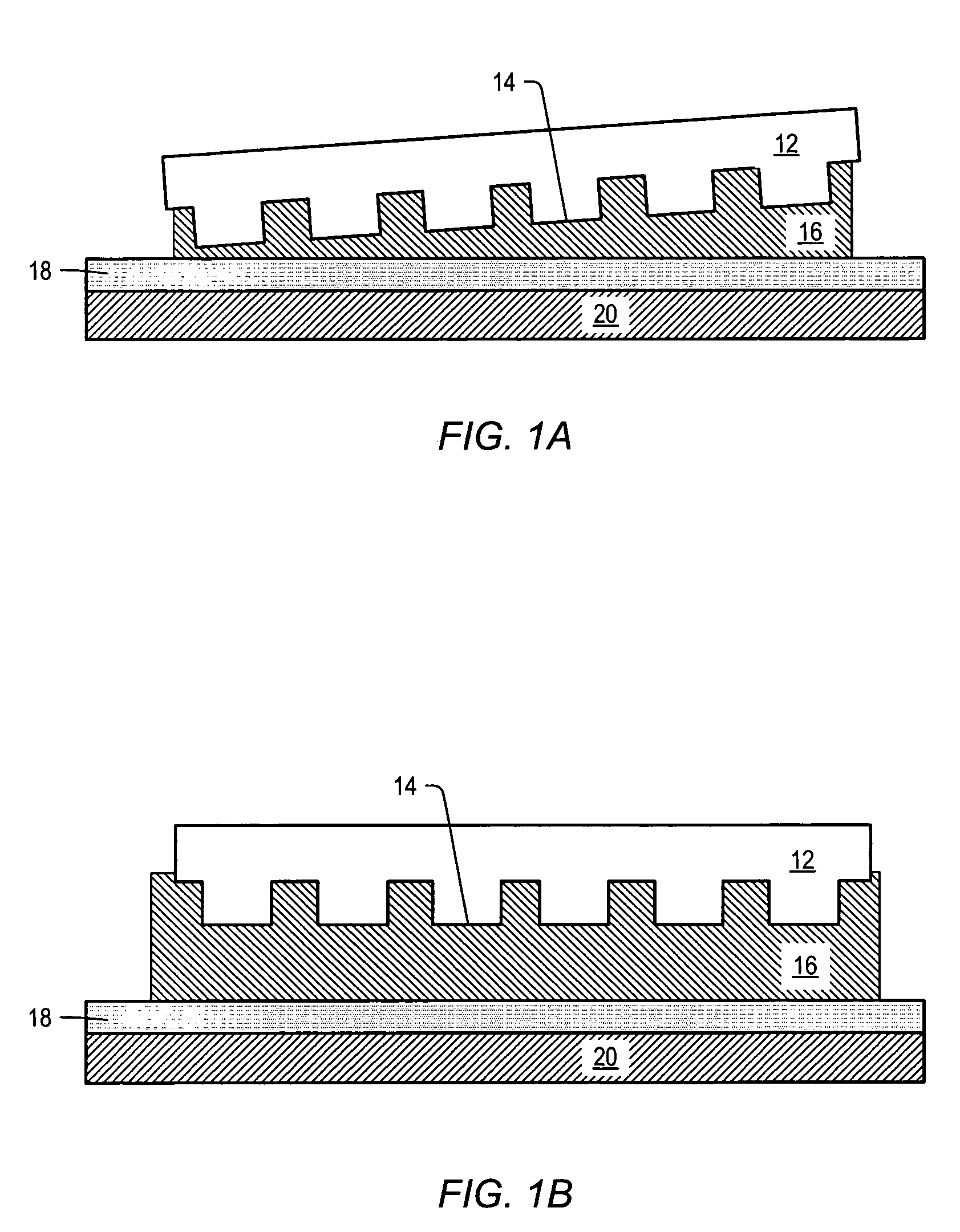
CROSS-REFERENCE TO RELATED APPLICATIONS[0001]The present application is a divisional of U.S. patent application Ser. No. 09 / 976,681 filed on Oct. 12, 2001 entitled “Template Design for Room Temperature, Low Pressure Micro- and Nanoimprint Lithography,” which claims priority to U.S. Provisional Patent Application No. 60 / 239,808 filed on Oct. 12, 2000 entitled “Template Design for Room Temperature, Low Pressure Micro- and Nanoimprint Lithography and Method for Sensing Gap or Film Thickness,” both of which are incorporated by reference herein.STATEMENT REGARDING FEDERALLY SPONSORED RESEARCH OR DEVELOPMENT[0002]The U.S. Government has a paid-up license in this invention and the right in limited circumstances to require the patent owner to license others on reasonable terms as provided for by the terms of N66001-98-18914 awarded by the Defense Advanced Research Projects Agency (DARPA).BACKGROUND OF THE INVENTION[0003]1. Field of the Invention[0004]The present invention relates to imprint...

Claims


Application Information

Patent Timeline
Patent Type & Authority Patents(United States)
IPC IPC(8): B29C59/02H01L21/027B29C35/08B29C37/00G03F7/00G03F9/00
CPCB29C35/0888B29C37/0053B29C43/003B82Y40/00G03F7/0002G03F9/00G11B5/855B82Y10/00B29C2035/0827B29C2043/025Y10S977/887B29C37/005B82B3/00G03F7/20
Inventor BAILEY, TODD C.CHOI, BYUNG-JINCOLBURN, MATTHEW E.SREENIVASAN, SIDLGATA V.WILLSON, CARLTON G.EKERDT, JOHN G.
Owner BOARD OF RGT THE UNIV OF TEXAS SYST
Learn More