Method for manufacturing bipolar plate and direct methanol fuel cell

a technology of bipolar plate and fuel cell, which is applied in the direction of cell components, final product manufacturing, sustainable manufacturing/processing, etc., can solve the problems of too thick 12/b> and thus too unwieldy to carry

Inactive Publication Date: 2007-06-12
NAN YA PRINTED CIRCUIT BOARD CORPORATION
View PDF36 Cites 33 Cited by
  • Summary
  • Abstract
  • Description
  • Claims
  • Application Information

AI Technical Summary

Problems solved by technology

First, the bipolar plate assembly 12 is too thick and thus too unwieldy to carry.

Method used


Image

  • Method for manufacturing bipolar plate and direct methanol fuel cell
  • Method for manufacturing bipolar plate and direct methanol fuel cell
  • Method for manufacturing bipolar plate and direct methanol fuel cell

Examples


Embodiment Construction

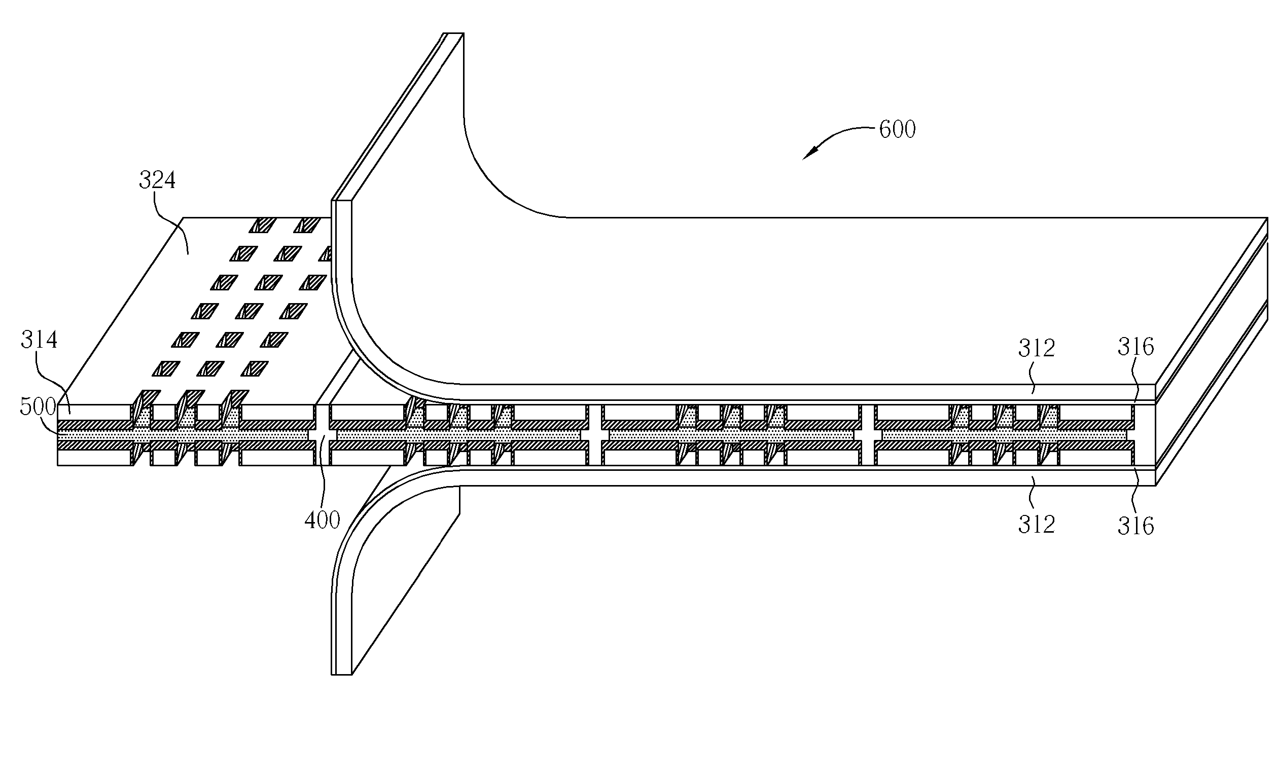
[0016]Please refer to FIG. 3 to FIG. 7. FIG. 3 to FIG. 7 are diagrams showing the method for fabricating a bipolar plate 300 of a DMFC according to the present invention.

[0017]As shown in FIG. 3, the fabrication of the bipolar plate 300 comprises providing a substrate, which includes a releasable copper carrier 312, providing a metal foil 314 disposed on top of the releasable copper carrier 312, and providing a release layer 316 that functions to bind the releasable copper carrier 312 and the metal foil 314 together. The metal foil 314 can be comprised of a plurality of copper plates. As shown in FIG. 4, a photoresist 318 is layered on the metal foil for defining an electrode plate area 322. Next, a copper etching process is performed as shown in FIG. 5 to etch the area of the metal foil 314 not covered by the photoresist 318 for forming a recess 319. Next, the photoresist 318 is removed as shown in FIG. 6. In order to prevent oxidation caused by direct contact between the electrode...


PUM

PropertyMeasurementUnit
temperatureaaaaaaaaaa
thicknessaaaaaaaaaa
thicknessaaaaaaaaaa

Abstract

A DMFC (direct methanol fuel cell) includes two bipolar plates, a membrane electrode assembly, a bonding layer, and a fuel container base. The bipolar plate is a releasable substrate that includes a releasable copper carrier, a release layer, and a metal foil. The bipolar / MEA assembly is formed by laminating the releasable bipolar, the MEA, and the bonding sheet, peeling off the release carrier, and printing a carbon ink or plating Au.

Description

BACKGROUND OF INVENTION[0001]1. Field of the Invention[0002]The present invention relates to a direct methanol fuel cell (DMFC), and more particularly, to a method for fabricating a releasable bipolar of the DMFC.[0003]2. Description of the Prior Art[0004]A fuel cell is an electrochemical cell in which a free energy change resulting from a fuel oxidation reaction is converted into electrical energy. Fuel cells utilizing methanol as fuel are typically called Direct Methanol Fuel Cells (DMFCs), which generate electricity by combining gaseous or aqueous methanol with air. DMFC technology has become widely accepted as a viable fuel cell technology that offers itself to many application fields such as electronic apparatuses, vehicles, military equipment, the aerospace industry, and so on.[0005]DMFCs, like ordinary batteries, provide DC electricity from two electrochemical reactions. These reactions occur at electrodes (or poles) to which reactants are continuously fed. The negative elect...

Claims


Application Information

Patent Timeline
Patent Type & Authority Patents(United States)
IPC IPC(8): C23F1/00H01M4/00H01M8/00
CPCC23F1/02H01M8/0206H01M8/0228H01M8/0213Y02E60/50Y02P70/50
Inventor LIU, YUNG-YISHANG, JAMES
Owner NAN YA PRINTED CIRCUIT BOARD CORPORATION
Why Eureka
Try Eureka