Wireless sensor system

a sensor system and wireless technology, applied in transmission systems, tire measurement, sustainable buildings, etc., can solve problems such as logistic problems, battery service, and complex wiring, and achieve the effect of costs, reducing the number of wires, and improving the service li

Inactive Publication Date: 2007-06-12
ENOCEAN
View PDF10 Cites 48 Cited by
  • Summary
  • Abstract
  • Description
  • Claims
  • Application Information

AI Technical Summary

Problems solved by technology

The wiring, which is often complex and thus costly, is problematic in this case.
However, these have the disadvantage that the batteries must be serviced.
Particularly where there are a large number of dev

Method used


Image

  • Wireless sensor system
  • Wireless sensor system

Examples


Embodiment Construction

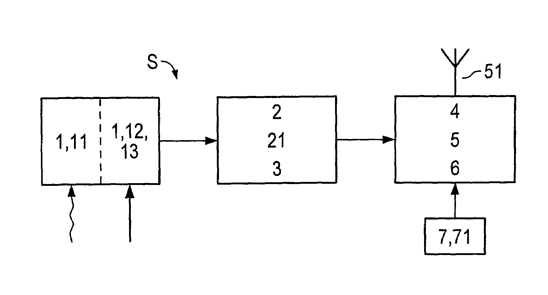
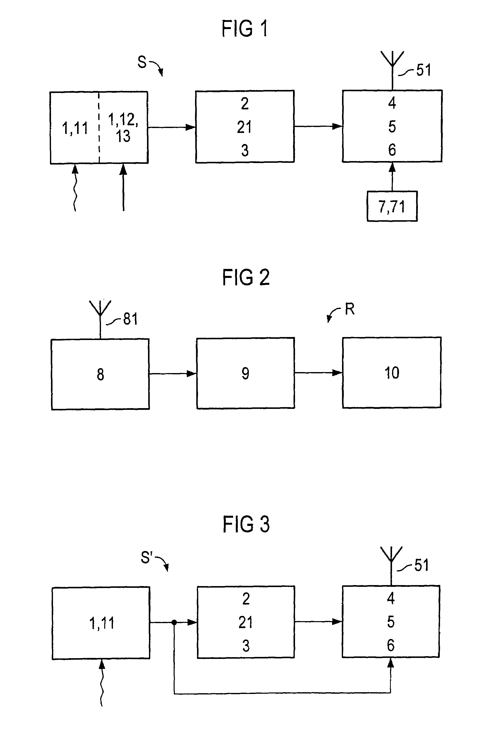
[0023]FIG. 1 shows a block diagram of a sensor system S for position finding.

[0024]The wire-free sensor system S passes on information by radio to actuators, bus systems or display elements, which are typically connected to the electrical mains system. The power for operation of the sensor system S together with the associated radio transmitter 5 is supplied from the ambient lighting and / or from the mechanical movement of the devices to be monitored, so that there is no need for a battery to operate it.

[0025]A voltage generator 1 in the form of a solar cell 11 (in general: a photovoltaic element) produces an electrical voltage when light falls on it. This is designed such that a voltage of about two volts is emitted even when the illumination intensities are low. For cost reasons, the solar cell 11 is preferably chosen to be sufficiently small that the processor controller 4 cannot be operated directly from it continuously. This is possible, for example, when a low frequency is used...


PUM


Abstract

A sensor system (S, S′) having a least one voltage generator (1, 11, 12, 13) for conversion of non-electrical energy to electrical energy. At least one energy store (2) is connected downstream from the voltage generator (1, 11, 12, 13). At least one voltage converter (3) is connected to the energy store (2) such that its output signal is suitable for operation of a processor controller (4). At least one sensor (7, 71) is provided, and at least one transmitter (5) enables wire-free transmission of transmission messages which can be produced by the processor controller (4) and which contain at least one measured value from the at least one sensor (7, 71). A timer circuit (6) is provided, which can be triggered as a function of a voltage level of the at least one energy store (2), and which activates the sensor system (S) in order to transmit at least one transmission message after a specific time interval.

Description

RELATED APPLICATION[0001]This is a U.S. National Stage of International Application No. PCT / DE02 / 03732 filed on 1 Oct., 2002.[0002]This patent application claims priority of German patent application no. 101 50 128.5 filed 11 Oct. 2001.[0003]The invention relates to a sensor system which is not connected by wire (“wire-free”), to a monitoring system based on this sensor system, and to two uses of the sensor system.BACKGROUND OF THE INVENTION [0004]Until now, environmental changes have mainly been detected by sensors which pass on state information via wire lines, and are at the same time supplied with electrical power via these wire lines. The wiring, which is often complex and thus costly, is problematic in this case.[0005]Battery-operated sensors are likewise known, which pass on the corresponding measured values by radio. However, these have the disadvantage that the batteries must be serviced. Particularly where there are a large number of devices to be monitored, the batteries ...

Claims


Application Information

Patent Timeline
IPC IPC(8): G08B1/08H04Q7/00G08C17/02H02N2/18G08C17/00
CPCG01D21/00G08C17/02H05B39/042Y02B20/14H05B47/11Y02B20/00
Inventor ALBSMEIER, ANDREBULST, WOLF-ECKHARTPISTOR, KLAUSSCHMIDT, FRANKSCZESNY, OLIVER
Owner ENOCEAN
Why Eureka
Try Eureka