
Efficient method and system for automatic discovery and verification of optimal paths through a dynamic multi-point meshed overlay network

a dynamic multi-point meshed overlay and optimal path technology, applied in the field of computer network routing, can solve the problems of reducing the transmission time of packets to the required destination node, conventional routing solutions that do not adapt to select optimal paths in the wan, and unable to accurately predict which path would reach the intended destination faster

Inactive Publication Date: 2007-06-12
JUMIPER NETWORKS INC
View PDF5 Cites 37 Cited by
  • Summary
  • Abstract
  • Description
  • Claims
  • Application Information

AI Technical Summary

Benefits of technology

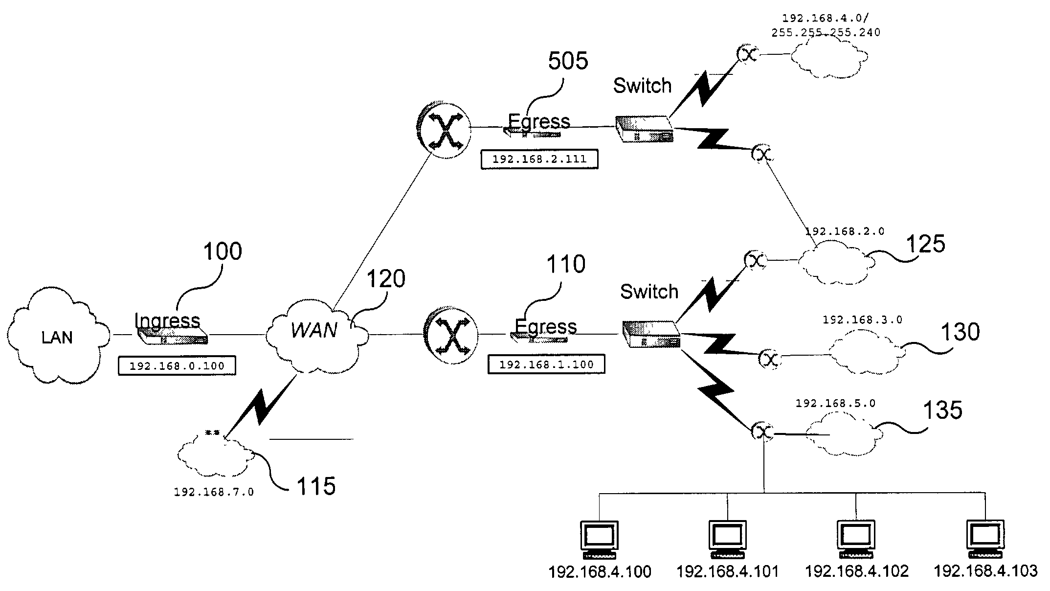
[0017]In one embodiment, the ingress router verifies the optimal overlay paths by sending a plurality of probe packets to each destination subnet. In one embodiment the egress router which receives these packets (and presumably advertised the destination to the ingress router) stops the probe packets and reports back to the ingress router that they were received. In another embodiment, the egress router allows multiple instances of a probe packet to be forwarded on to another egress router downstream to allow the ingress router to verify a cascaded meshed overlay network.

Problems solved by technology

Without being able to calculate the entire path taken by the packet, a router may inadvertently send a packet down a path which may dead-end or may significantly degrade transmission times of the packet to the required destination node.
In addition, conventional routing solutions do not adapt to select an optimal path in the WAN.
In addition to the creation of lost or underliverable packets due to a conventional router's poor routing choices, routers may also have different transmission times depending on which router they are sending or receiving data from.
Since conventional networks are commonly composed of a variety of different speed lines, it is possible for two separate paths through the WAN to reach the same destination at different times. Based on the local information available to a conventional router, it would be unable to accurately predict which path would reach the intended destination quicker.
Conventional routers are unable to recognize when a router closer to the required destination has been taken off line or has slowed down significantly.
Since it cannot detect disabled routers further downstream, a conventional router would not be able to intelligently choose a different path to avoid the disabled router.
As such, the conventional router cannot efficiently choose its route for any given data packet.

Method used


Image

  • Efficient method and system for automatic discovery and verification of optimal paths through a dynamic multi-point meshed overlay network
  • Efficient method and system for automatic discovery and verification of optimal paths through a dynamic multi-point meshed overlay network
  • Efficient method and system for automatic discovery and verification of optimal paths through a dynamic multi-point meshed overlay network

Examples


Embodiment Construction

[0025]A preferred embodiment of the present invention is now described with reference to the figures where like reference numbers indicate identical or functionally similar elements. Also in the figures, the left most digit of each reference number corresponds to the figure in which the reference number is first used.

[0026]Reference in the specification to “one embodiment” or to “an embodiment” means that a particular feature, structure, or characteristic described in connection with the embodiments is included in at least one embodiment of the invention. The appearances of the phrase “in one embodiment” or “in an embodiment” in various places in the specification are not necessarily all referring to the same embodiment.

[0027]Some portions of the detailed description that follows are presented in terms of algorithms and symbolic representations of operations on data bits within a computer memory. These algorithmic descriptions and representations are the means used by those skilled ...


PUM


Abstract

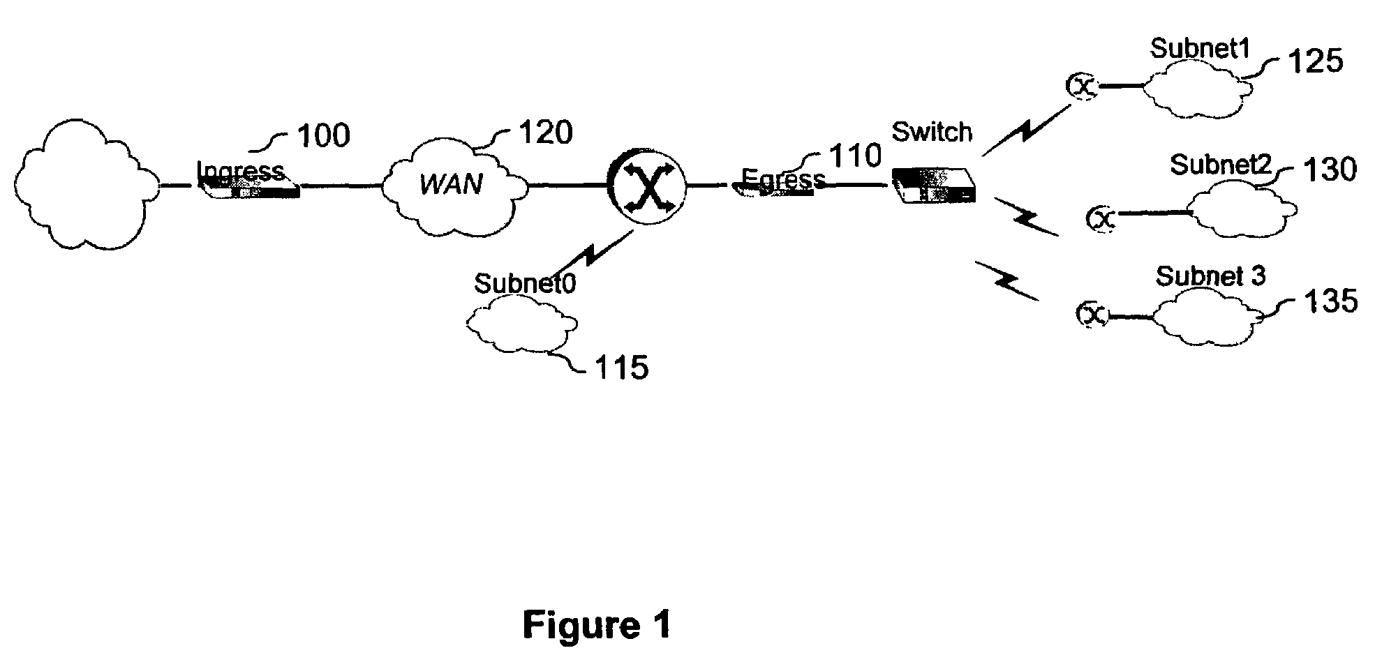
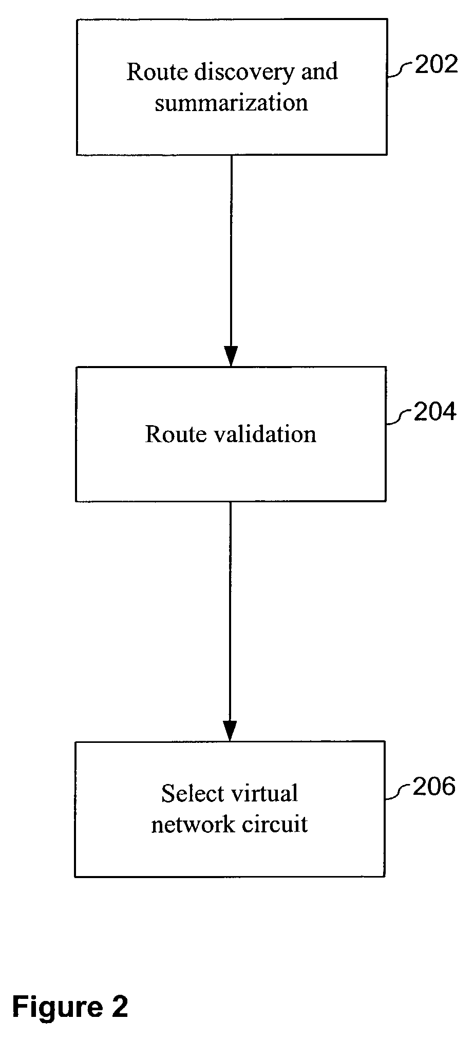
The present invention provides an efficient system and method for routing information through a dynamic network. The system includes at least one ingress point and one egress point. The ingress and egress point cooperate to form a virtual circuit for routing packets to destination subnets directly reachable by the egress point. The egress point automatically discovers which subnets are directly accessible via its local ports and summarizes this information for the ingress point. The ingress point receives this information, compiles it into a routing table, and verifies that those subnets are best accessed by the egress point. Verification is accomplished by sending probe packets to select addresses on the subnet. Additionally, the egress point may continue to monitor the local topology and incrementally update the information to the ingress to allow the ingress to adjust its compiled routing table.

Description

RELATED APPLICATIONS[0001]This application claims priority under 35 U.S.C. § 119(e) to U.S. Provisional Application serial No. 60 / 314,692, entitled “Efficient Method and System for Automatic Discovery and Verification of Optimal Paths through a Dynamic Multi-point Meshed Overlay Network”, filed on Aug. 24, 2001, the subject matter of which is incorporated by reference in its entirety herein.[0002]This application is also related to U.S. patent application Ser. No. 09 / 915,939, entitled “Network Architechture and Methods For Transparent On-Line Cross-Sessional Encoding and Transport of Network Communication Data”, file on Jul. 25, 2001 by Amit P. Singh, the subject matter of which is incorporated by reference in its entirety herein.[0003]This application is also related to U.S. patent application Ser. No. 09 / 872,184, entitled “System and Method for Incremental and Continuous Data Compression”, filed on May 31, 2001 by Amit P. Singh, the subject matter of which is incorporated by refer...

Claims


Application Information

Patent Timeline
Patent Type & Authority Patents(United States)
IPC IPC(8): H04L12/56
CPCH04L45/02H04L45/124H04L45/125H04L45/26H04L45/64
Inventor BHARALI, ANUPAM A.SINGH, BALRAJSAMPAT, MANISH H.SINGH, AMIT P.BATRA, RAJIV
Owner JUMIPER NETWORKS INC
Learn More