Unlock instant, AI-driven research and patent intelligence for your innovation.

Screening method for overlapping sub-images

Inactive Publication Date: 2007-06-12
AGFA NV
View PDF18 Cites 4 Cited by
  • Summary
  • Abstract
  • Description
  • Claims
  • Application Information

AI Technical Summary

Benefits of technology

[0024]It is an object of the invention to provide a method for the reproduction of an original image including high quality joining of two sub-images that are printed sequentially by one imaging device or that are printed by two different imaging devices.SUMMARY OF THE INVENTION

Problems solved by technology

A print head is generally not capable to generate at once the complete image on the image carrier.
An imaging device capable to address that large number of microdots at once and at that resolution would be too costly.
Due to the cost of some complex devices, it is sometimes too expensive to provide a print head having a length equal or larger than the width of the recording material.
For some technologies it is even impossible to make a good quality print head of a large size.
As such, the shorter print head cannot address instantly all microdots arranged on one line running from one side to the opposite side of the image carrier.
Sequentially printing the image in bands or sub-images may give the following problems.1. When image bands do not exactly join together it is possible that a distinct white line in between the printed bands becomes clearly visible as an image defect.
On the other hand, when the image bands overlap, a clearly visible dark line disturbs the image.2. Even when print bands join perfectly along the length, a slight mismatch in the position of the bands along this length can cause visible artefacts.
The very accurate positioning systems, needed to solve the above problem, are too expensive to install in the printers destined to the consumer market.

Method used


Image

  • Screening method for overlapping sub-images
  • Screening method for overlapping sub-images
  • Screening method for overlapping sub-images

Examples


Embodiment Construction

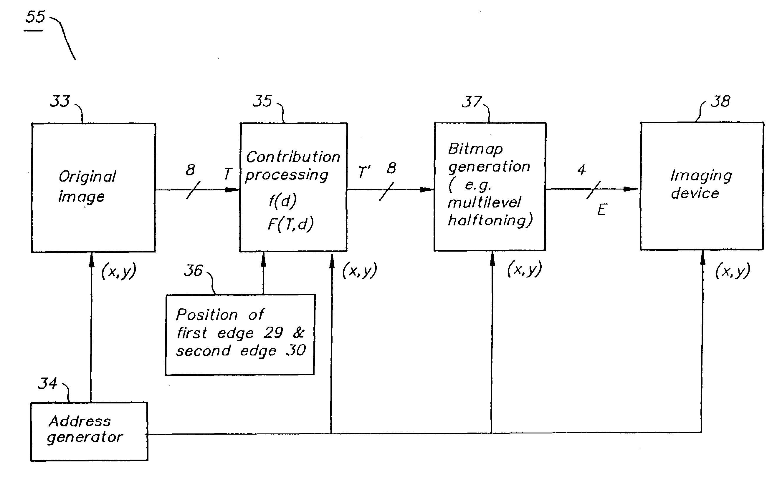
[0052]FIG. 1 shows a first sub-image 21 and a second sub-image 22. The first sub-image or image band 21 may be generated by linewise exposure, i.e. parallel to the line direction 24, e.g. by a DEP device having a single row of apertures or by an inkjet device having a row of nozzles. After printing the first line, the imaging device advances according to the printing direction 23 or the image carrier on which the image is to be printed advances in the opposite direction. By iteratively printing and advancing, the sub-image 21 is completely printed. Thereafter, the imaging device is moved towards the second sub-image 22 or the image carrier is displaced relative to the imaging device, such that the imaging device can now print the first line of the second sub-image 22 etc. The two sub-images 21 and 22, materialised by two parallel bands according to this example in FIG. 1, must be joined to get a larger image, e.g. for the production of a poster, larger than the printing capability o...


PUM


Abstract

A method and system for reproducing an image on a carrier, the method includes: generating a conjoined first and second sub-image, each representative for a portion of the image; defining an overlap region where both sub-images give a contribution to the internal optical density of the carrier; dividing the overlap region in a partition of microdots; establishing for each sub-image a peripheral edge in the overlap region; increasing the contribution by the first sub-image from the peripheral edge of the first sub-image to the peripheral edge of the second sub-image; and assigning to at least one microdot an intermediate microscopic density different from a minimum or maximum microscopic density of microdots; wherein the contribution increases the microscopic density of the microdots by density steps smaller than half the difference between the minimum and maximum microscopic densities of the microdots.

Description

FIELD OF THE INVENTION[0001]The present invention relates to an image reproduction method by joining adjacent images, such as two or more image bands, in an image generating device, such as a printer.BACKGROUND OF THE INVENTION[0002]Nowadays many types of image generating devices exist, including phototypesetters, imagesetters, lithographic printers and electronic printers for printing electronic (colour) images. The generated images may be e.g. latent, visible or lithographic and are generated on a suitable image carrier. An image carrier may be paper, a transparent PET (polyethyleenterephtalate) material, photographic material, an electrophotographic drum or a lithographic printing plate etc. A non-visible image usually undergoes a process to generate a visible image from it: a latent image may be developed; a lithographic image, comprising ink accepting and ink repellent zones, may be provided with ink, which is transferred to a paper image carrier to render a visible image.[0003...

Claims


Application Information

Patent Timeline
IPC IPC(8): G06K9/40G06K9/36H04N1/405H04N1/409
CPCH04N1/3876H04N1/1911
Inventor BRODDIN, DIRKVERBRUGGEN, MARIOTAVERNIER, SERGE
Owner AGFA NV