Hydraulic apparatus

a technology of hydraulic apparatus and hydraulic valve, which is applied in the direction of fluid couplings, servomotors, sustainable manufacturing/processing, etc., can solve the problems of limited use and application range, inability to be practical, and limit the increase of pressure, so as to achieve effective opening and closing

Inactive Publication Date: 2007-06-19
SAXA +1
View PDF10 Cites 13 Cited by
  • Summary
  • Abstract
  • Description
  • Claims
  • Application Information

AI Technical Summary

Benefits of technology

[0012]The on-off valve can be effectively opened and closed by use of a controller for controlling the on-off valve, which is comprised of a microcomputer or the like.
[0014]Furthermore, since the hydraulic pump motor is driven by the hydraulic power from the oil pressure source to store the energy in the inertial body, only one oil pressure source can be shared even in a case where a plurality of loads are provided and where for each load there are provided a hydraulic pump motor, an inertial body, a second oil path, an unloading oil path, an on-off valve, a valve for prevention of backflow, and a third oil path. Namely, the operating oil from the oil pressure source can be distributed through branch pipes branched from the first oil path, to the respective hydraulic pump motors, so as to enable independent control of the individual loads.

Problems solved by technology

However, the hydraulic system making use of the oil impact causes a considerable loss and has a limit to increase of pressure, and thus it is considered not to be practical.
As described above, the hydraulic system 1 disclosed in Laid-Open No. 2003-130006 provides the excellent effect of capability of supplying the operating oil at the higher pressure to the load 6, but also has a problem that usage and application ranges are limited.
In such cases, the rubber hoses or the like expand and contract to lower efficiency, and it is difficult to adopt the hydraulic system 1.
In addition, in cases where there are a plurality of loads 6 and desires for individual control of the loads, it is necessary to prepare a plurality of hydraulic systems 1 and it is difficult to reduce the number of parts by common use of components.

Method used


Image

  • Hydraulic apparatus
  • Hydraulic apparatus
  • Hydraulic apparatus

Examples


Embodiment Construction

[0022]Preferred embodiments of the present invention will be described below in detail with reference to the drawings. Identical or equivalent portions will be denoted by the same reference symbols throughout the drawings, without redundant description.

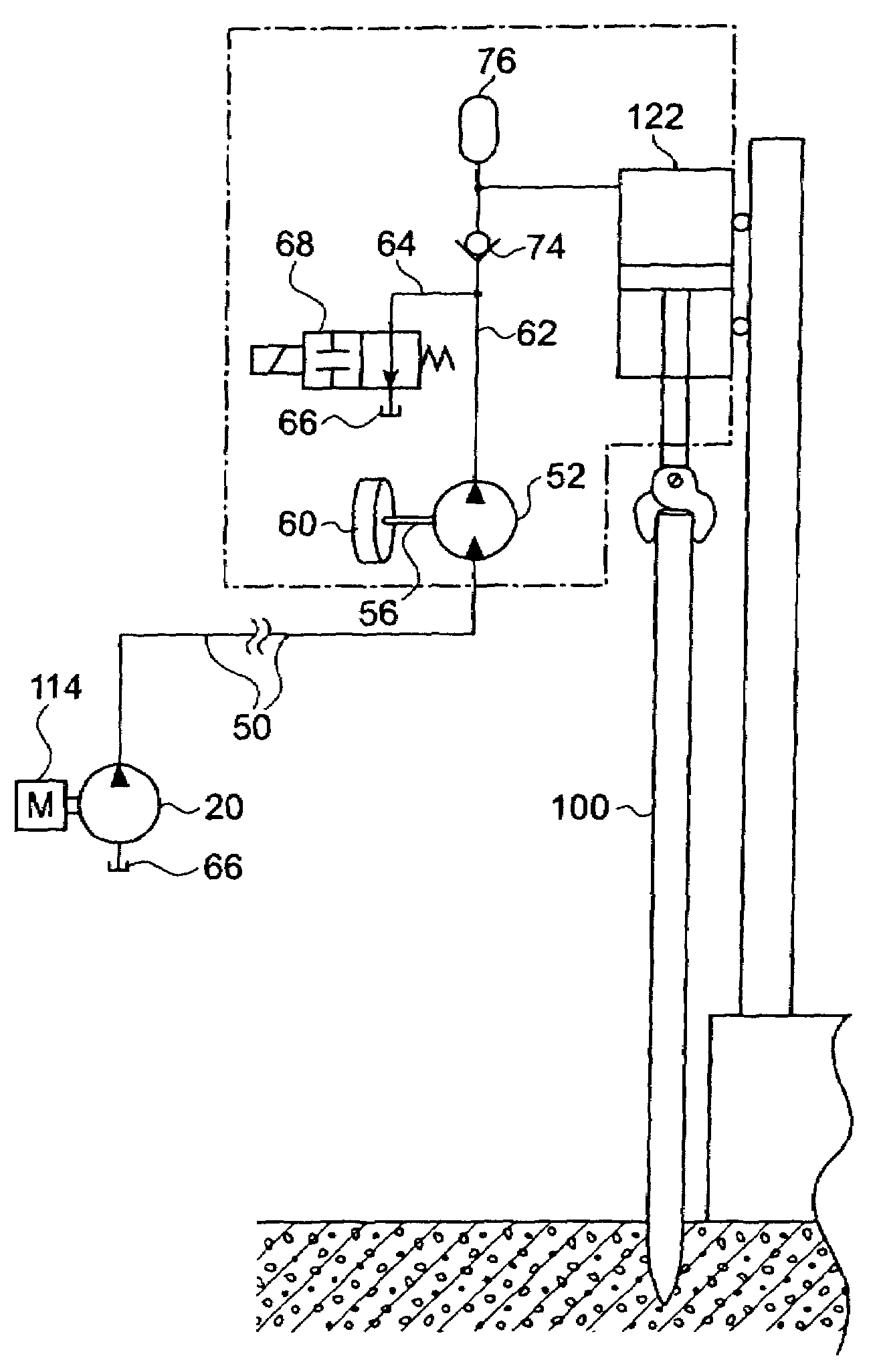
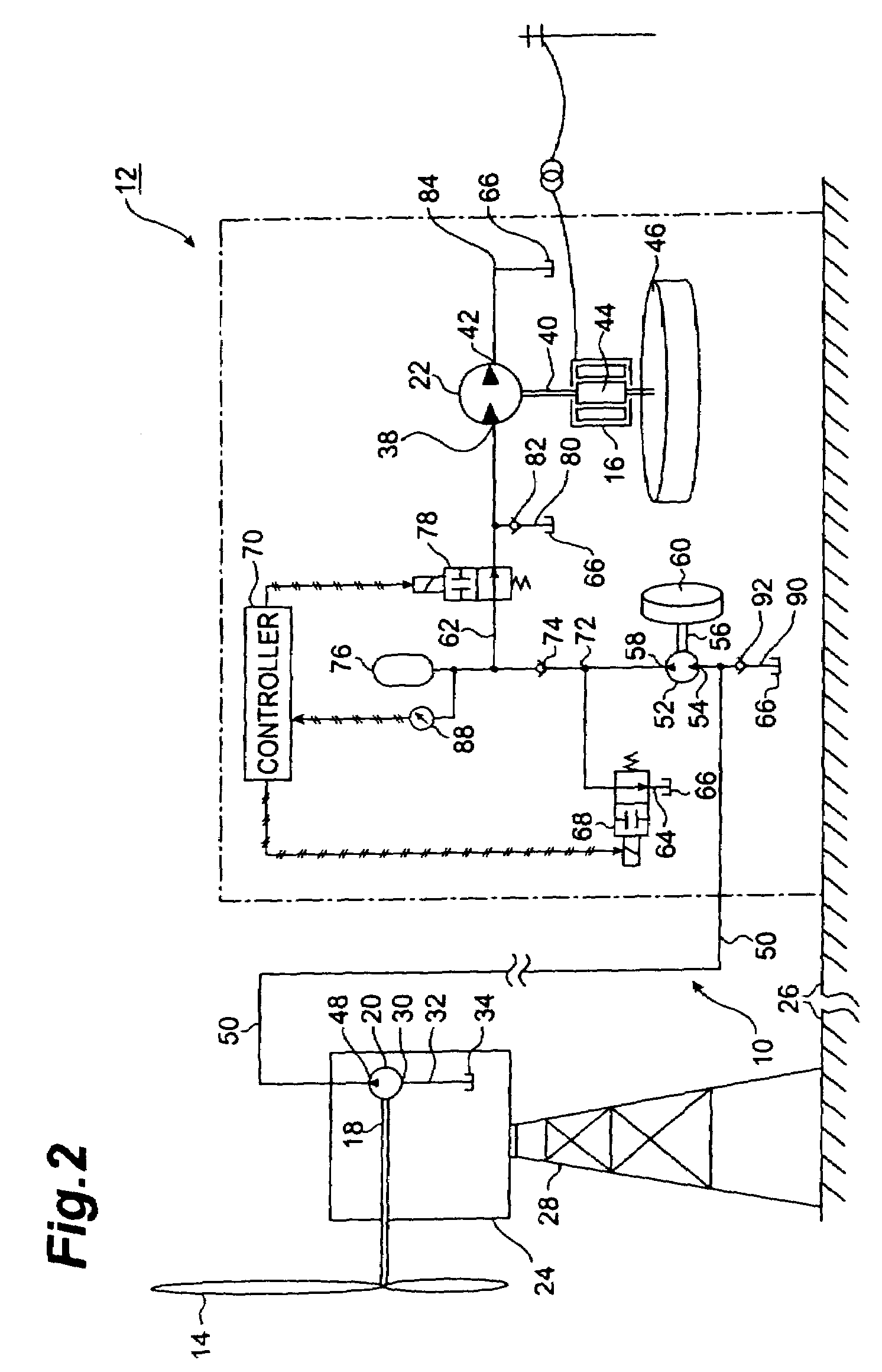
[0023]FIG. 2 is a schematic illustration showing a wind power generator 12 to which a hydraulic system 10 according to the present invention is applied. The represented wind power generator 12 uses a propeller type windmill (driving source) 14 and is arranged to once convert a mechanical power generated with rotation of the windmill 14 by wind, to a hydraulic power and to thereafter convert this hydraulic power again to a mechanical power so as to rotate a rotary shaft of electric generator 16. For that purpose, the hydraulic system 10 in the represented wind power generator 12 is provided with a hydraulic pump 20 for converting the mechanical power to the hydraulic power, a rotary shaft 18 of which is connected to the windmill 14, an...


PUM


Abstract

A hydraulic system 10 of the present invention has a hydraulic pump driven by a driving source 14, a hydraulic pump motor 52 driven by an operating oil discharged from the hydraulic pump and flowing in an oil path 50, an inertial body 60 connected to a rotary shaft of the hydraulic pump motor, an oil path 62 connected between an outlet port of the hydraulic pump motor and a load 22, an unloading oil path 64 branched from the oil path 62, and an on-off valve 68 inserted in the unloading oil path. In this configuration, as the on-off valve is opened and closed, a high pressure is generated in the oil path 62 by making use of kinetic energy of the inertial body. The inertial body is driven by hydraulic power and the inertial body is separated from the driving source, which also provides an effect of increasing degrees of freedom for an instrument layout.

Description

TECHNICAL FIELD[0001]The present invention relates to a hydraulic system capable of extracting a hydraulic power greater than that generated by an oil pressure source.BACKGROUND ART[0002]Examples of the hydraulic systems of the above type include those disclosed, for example, in Japanese Patent Applications Laid-Open No. 6-287952 and Laid-Open No. 2003-130006.[0003]The hydraulic system disclosed in Japanese Patent Application Laid-Open No. 6-287952 relates to a press-in pile driver and is characterized in that an unloading oil path is branched from an oil path between a hydraulic pump as an oil pressure source and a hydraulic cylinder as a load and an on-off valve is inserted in the unloading oil path. The Application Laid-Open No. 6-287952 describes that in this configuration the on-off valve is instantly opened and closed to apply an oil impact to an operating oil flowing from the hydraulic pump to the hydraulic cylinder, whereupon the pressure of the operating oil can be made hig...

Claims


Application Information

Patent Timeline
Patent Type & Authority Patents(United States)
IPC IPC(8): F16D31/02F03D9/00F03D9/02F03D11/02F15B1/02F15B1/033F15B11/02
CPCF03D9/02F03D11/02F15B1/024F15B1/033F05B2260/406Y02E10/722F05B2260/421F03D15/00F03D9/12Y02E60/16Y02E10/728F03D9/25F03D13/20Y02E10/72Y02P80/10Y02E70/30
Inventor SUZUKI, SHIGERUSHIMADA, SATORUYAMANO, TAKAHIROSEKI, SUMIKOITOH, TAKAHIKO
Owner SAXA
Why Eureka
Try Eureka