Vessel with a multi-mode hull

a multi-mode, hull technology, applied in the field of multi-mode hulls, can solve the problems of limited range of high-speed mode of operation, and achieve the effects of reducing radar and infrared signature, excellent seakeeping, and increasing the payload of the ship

Active Publication Date: 2007-06-19
LOCKHEED MARTIN CORP
View PDF29 Cites 8 Cited by
  • Summary
  • Abstract
  • Description
  • Claims
  • Application Information

AI Technical Summary

Benefits of technology

[0010]As the payload in the ship increases beyond the light to moderate payload of the Shallow Draft Mode (Catamaran mode), the draft for the ship correspondingly increases since the displacement of the ship must equal the total weight of the ship plus the payload for the ship to remain afloat. The shape of the ship's hulls enables the ship to operate as a small-waterplane-area twin hull (SWATH), a hullform type well known to provide excellent seakeeping in high seas. In this Moderate Draft (SWATH) Mode, the ship is optimized to carry moderate to heavy payloads for long distances at moderate speeds in deep water in seas ranging from calm- to high-sea states.4) Low Freeboard Mode (Also Known as Stealth Mode)
[0011]A Low Freeboard Mode is achieved by further increasing the payload of the ship beyond the Moderate Draft Mode or by adding ballast to the ship in the Moderate Draft Mode such that the center portion of the ship between the two side hulls touches the water. By eliminating the air gap between the water and the underside of the center portion of the ship, the “shadow” created by the air gap is eliminated and the ship has a reduced radar and infrared signature and therefore has improved stealth performance. This mode is optimized for low-speed operations in areas of potentially high-threat detection activity with moderate to heavy payloads.

Problems solved by technology

However, the limited fuel capacity needed to achieve the light payload results in limited range for this high-speed mode of operation.

Method used


Image

  • Vessel with a multi-mode hull
  • Vessel with a multi-mode hull
  • Vessel with a multi-mode hull

Examples


Embodiment Construction

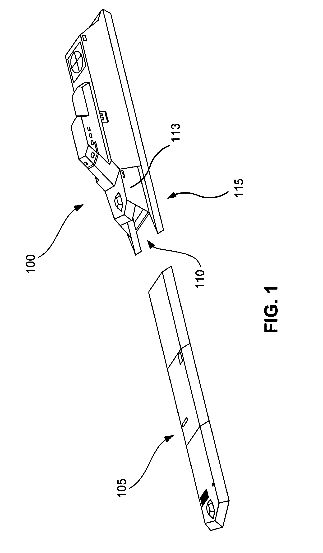
[0018]FIG. 1 is an isometric view diagram of a multi-mission ship 100 and an associated mission module 105 according to an embodiment of the invention. The ship 100 includes a hull structure or frame 115 that is designed to accept one or more mission modules 105 (only one shown in FIG. 1). The frame 115 includes two lower hull portions 112a and 112b (called struts hereinafter) that extend down from a main body 113, (one strut and lower hull 112a extending down from the port side and one strut and lower hull 112b extending down from the starboard side) such that a receptacle or bay 110 is enclosed by the struts 112a and 112b and the main body 113. The bay 110 creates a cavity such that water is free to flow in and out of the bay area as the hull portions 112a and 112b are only coupled to the main body 113 which stays above the surface of the water because of the buoyancy of the struts 112a and 112b. As such, a small watercraft or other floating objects may traverse into the bay 110, ...


PUM


Abstract

A ship having a multi-mode hull where the draft, seakeeping, and payload-carrying capacity are varied to match the requirements of the required mission. For example, the ship has a hull with first and second hull portions and with an interconnecting hull structure, and has a ballasting system within the hull portions and operable to adjust the draft of the vessel in conjunction with the payload carried by the ship so that the ship can perform a designated mission. The hull is designed to have an adjustable hull depth according to the payload carried to perform the mission and augmented by the ballasting system so as to optimize draft, and thus hull mode, to meet mission requirements. As a result, the ship operates in four distinct modes as follows: very shallow draft (logistics mode), shallow draft (catamaran mode), moderate draft (SWATH mode), and deep draft (stealth / low-freeboard mode).

Description

CLAIM OF PRIORITY[0001]This application claims priority to U.S. Provisional Application Ser. No. 60 / 426,070 filed on Nov. 12, 2002, which is incorporated by reference.CROSS REFERENCE TO RELATED APPLICATION[0002]This application is related to U.S. patent application Ser. No. 10 / 712,777 entitled MISSION MODULE SHIP DESIGN and Ser. No. 10 / 712,987 entitled METHOD AND SYSTEM FOR MISSION MODULE SWAPPING IN A VESSEL, which have a common filing date and owner, and which are in by reference.BACKGROUND OF THE INVENTION[0003]Modern Naval ships are typically designed to perform multiple types of missions, and are, therefore, referred to as “multi-mission” ships. For example, suppose a ship is designed for anti-submarine warfare, littoral warfare, and anti-mine warfare. Such a ship may include a deck that has a respective command / control station for each type of mission, i.e., a station for anti-submarine warfare, a station for littoral warfare, and a station for anti-mine warfare. The ship may ...

Claims


Application Information

Patent Timeline
Patent Type & Authority Patents(United States)
IPC IPC(8): B63B9/08B63B1/10B63B1/12B63B3/08B63B25/00B63B35/42
CPCB63B1/107B63B1/121B63B35/42Y02T70/14B63B25/006B63B3/08Y02T70/10
Inventor SCHMIDT, TERRENCE W.NOLAND, GARY M.MANNINO, ANTHONY J.COBB, BRUCE W.
Owner LOCKHEED MARTIN CORP
Why Eureka
Try Eureka