Flush box type multi-mode stabilization device

An anti-rolling device and multi-modal technology, applied in the direction of reducing ship motion through displacement, can solve the problems of frequent swinging rudder blades, increasing sailing resistance, and not too many actual ship applications

Inactive Publication Date: 2016-06-01
王涵
View PDF5 Cites 6 Cited by
  • Summary
  • Abstract
  • Description
  • Claims
  • Application Information

AI Technical Summary

Problems solved by technology

Both the passive anti-rolling tank and the active anti-rolling tank need to occupy a large volume in the tank. The passive anti-rolling tank has an obvious anti-rolling effect in the harmonic roll area, and may increase the roll in the non-harmonic roll area. The controllable passive anti-rolling tank On the basis of the passive water tank, the rolling water tank adjusts the speed and phase of the water flow in the tank to improve the anti-rolling effect. The anti-rolling effect of a well-designed controllable passive anti-rolling water tank can reach 50%, and the anti-rolling water tank The design of the ship must be carried out simultaneously with the overall design of the hull, and the control system is generally provided by a professional manufacturer; the rudder anti-rolling device is implemented by using the stern rudder, which cleverly utilizes the difference between the steering motion and the rolling cycle, and can control the steering simultaneously. Achieving the purpose of anti-rolling seems to be very cost-effective on the surface, but anti-rolling requires frequent swinging of the rudder blades, ordinary steering gears are not competent, and special steering gears need to be replaced, and the effect of rudder stabilizati

Method used


Image

  • Flush box type multi-mode stabilization device
  • Flush box type multi-mode stabilization device
  • Flush box type multi-mode stabilization device

Examples


Embodiment Construction

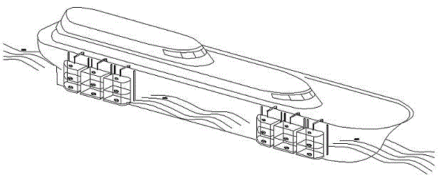
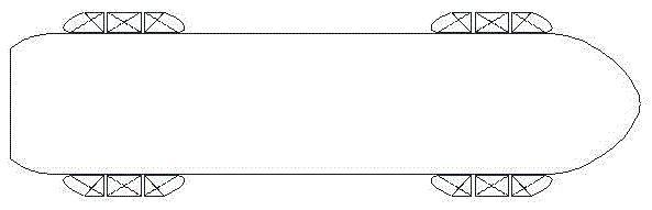
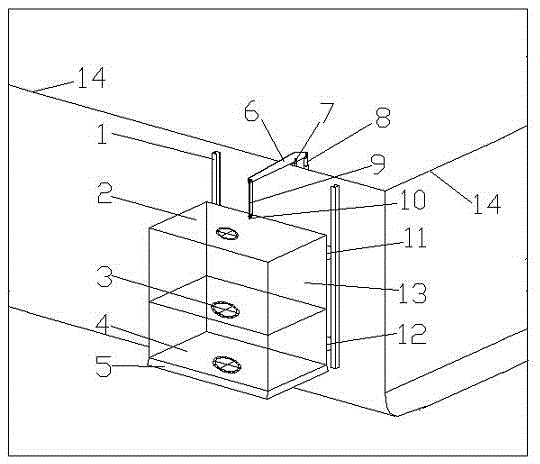
[0028] Such as Figure 1 to Figure 15As shown, the punching box type multi-mode anti-rolling device includes the punching box top plate 2, the middle partition plate 3, the punching box bottom plate 4, the rocker arm 6, the driving power device 8, the connecting rod 9, the connecting shaft 10, the upper roller 11, Lower roller 12 and box body 13, box top plate 2 and box bottom plate 4 are respectively installed on the upper and lower ends of box body 13, middle partition plate 3 is installed in box body 13, one end of connecting rod 9 is connected with rocking arm 6, and the other One end is connected to the box body 13 through the connecting shaft 10, the driving power device 8 is connected to the rocker arm 6, the upper roller 11 and the lower roller 12 are respectively installed on the back of the box body 13, and the anti-rolling device is installed on the outboard of the ship. It is connected with the hull through the rocker arm. The track 1 is installed on the hull 14. T...


PUM


Abstract

The invention discloses a flush box type multi-mode stabilization device, comprising a box body, a flush box top board, a middle partition, a flush box bottom board, a rocking arm, a driving power device, a connecting rod, a connecting rotary shaft, upper rollers and lower rollers.The flush box top board and the flush box bottom board are mounted at upper and lower ends of the box body, respectively, the middle partition is mounted in the box body, one end of the connecting rod is connected with the rocking arm, the other end of the connecting rod is connected to the box body through the connecting rotary shaft, the driving power device is connected with the rocking arm, the upper rollers and the lower rollers are mounted respectively on the back of the box body, the stabilization device is connected with a hull through the rocking arm, the hull is fitted with rails, and the upper and lower rollers of the stabilization device move up and down along the rails.The flush box type multi-mode stabilization device has clear mechanical principle of stabilization and high efficiency, is applicable to ships at a speed and at zero speed, is free of increasing hull draft or reducing original ship stability, is convenient to mount and maintain, and is suitable for standard and modular design and convenient to manufacture in parallel.

Description

technical field [0001] The invention relates to a punching box type multi-mode anti-rolling device. Background technique [0002] When ships and marine engineering floating structures are sailing or operating on the sea, there will inevitably be sway caused by wind and waves, including roll, pitch, heave (heave), yaw, etc. Swing will increase the load of the ship and reduce the operation of the ship. Efficiency, causing dizziness to passengers and crew, and even causing capsizing accidents in severe cases, the ship anti-rolling device is a general term for a type of special equipment that eliminates or slows down the ship’s swaying. There are two types of heeling moment, which are divided into two types: passive and active according to whether the anti-rolling device needs to be powered from the outside. Among them, there are no more than 10 types that are more classic and widely used. For example, the bilge keel is simple in structure, Low initial investment, good adaptabi...

Claims


Application Information

Patent Timeline
IPC IPC(8): B63B39/02
CPCB63B39/02
Inventor 王涵
Owner 王涵
Why Eureka
Try Eureka