
Composite tunnel anchorage structure

A tunnel anchor and composite technology, which is used in the installation of bolts, mining equipment, and earth-moving drilling, etc., can solve the problems of conservative engineering measures, slope instability, and weak slopes that are not easy to carry the main cable, and achieve a clear mechanical principle. , the effect of simple structure

Pending Publication Date: 2021-11-26
WUHAN UNIV OF SCI & TECH
View PDF0 Cites 0 Cited by
  • Summary
  • Abstract
  • Description
  • Claims
  • Application Information

AI Technical Summary

Problems solved by technology

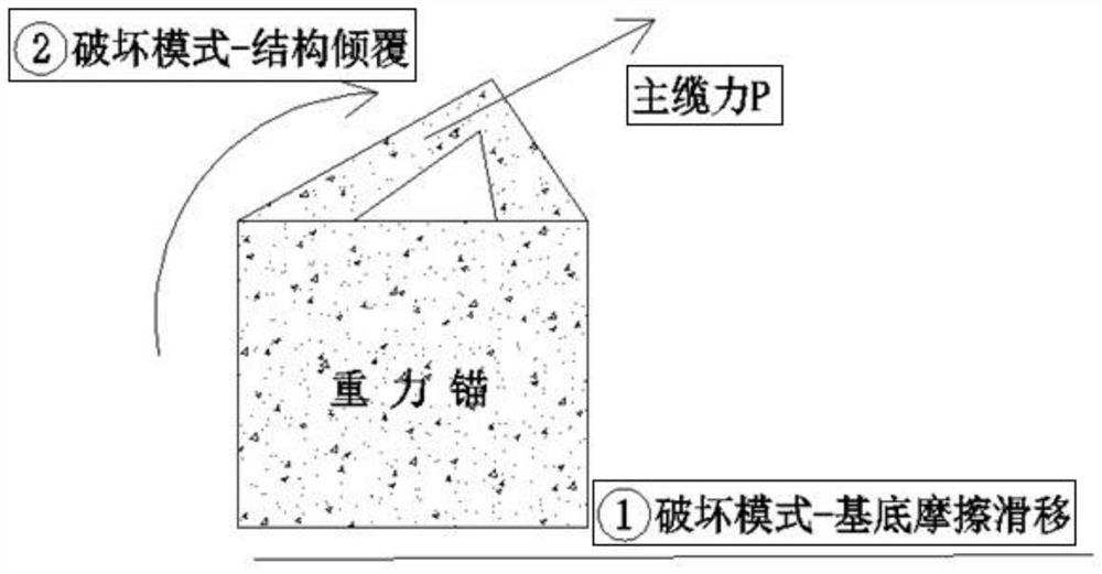
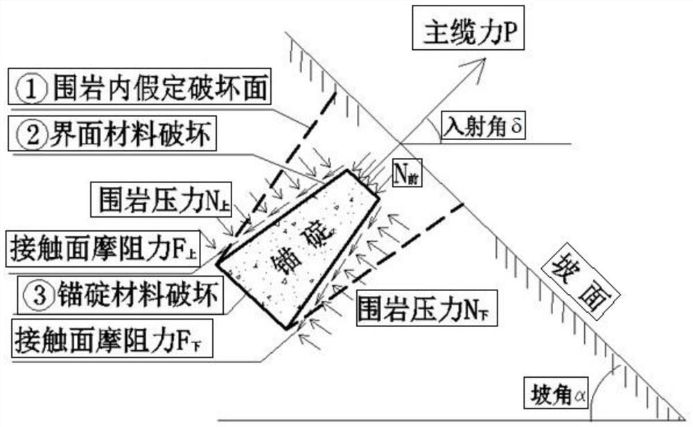
[0008] Aiming at the existing defects in the application of gravity anchor and tunnel anchor engineering, a composite tunnel anchor structure can effectively solve the problem that such debris or broken weak slopes are not easy to carry the main cable, and it is easy to cause slope damage after loading. The problem of instability has greatly improved the current situation of single anchorage design method and conservative engineering measures, effectively improved the level of engineering structure design in engineering practice, and can greatly reduce engineering costs

Method used


Image

  • Composite tunnel anchorage structure
  • Composite tunnel anchorage structure
  • Composite tunnel anchorage structure

Examples


Embodiment 1

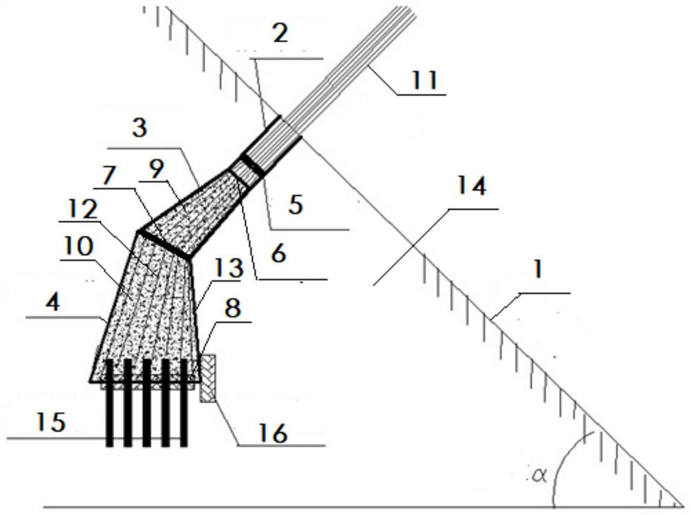
[0036] like image 3 , a composite tunnel anchorage structure, set in the rock layer 14 of the slope sliding surface 1, including the main cable access hole 2 parallel to the incident direction of the main cable 11, which is formed by successive excavation of the main cable access hole 2 Scattering room 3, wedge-shaped room 4, the average cross-sectional area of ​​scatter room 3 is A=30m 2 And loose cable room 3 lower end to the length of upper end is a=10m, and the base area of ​​wedge-shaped room 4 is B=50m 2 And the height is b=20m, after the excavation of the main cable access hole 2, loose cable room 3, and wedge-shaped room 4 is completed, the surrounding rock support layer 13 of the chamber is prepared by means of anchor spraying, etc., and the main cable access hole 2 is installed. There is a scatter saddle 5, and the end of the scatter chamber 3 close to the main cable access hole 2 is provided with a guide 6, the guide 6 includes a honeycomb structure composed of mu...


PUM


Abstract

The invention discloses a composite tunnel anchorage structure. The composite tunnel anchorage structure comprises a main cable access hole, a cable scattering chamber and a wedge-shaped chamber; a cable scattering saddle is installed in the main cable access hole, and a guiding member is arranged at the end, close to the main cable access hole, of the cable scattering chamber; a steering member is arranged on the interface of the cable scattering chamber and the wedge-shaped chamber, an anchorage device is arranged on a base face of the wedge-shaped chamber, and a front anchor block is arranged in the cable scattering chamber; a rear anchor block is arranged in the wedge-shaped chamber, the central axis of the cable scattering chamber coincides with the central axis of the main cable access hole, and the included angle between the central axis of the wedge-shaped chamber and the horizontal plane is larger than the incident angle of a main cable; the main cable is scattered into steel strands from the main cable access hole through the cable scattering saddle; and all the steel strands are evenly scattered into the section of the cable scattering chamber through the guiding member and penetrate the front anchor block, then are steered by the steering member and evenly dispersed into the section of the wedge-shaped chamber, and finally pass through the rear anchor block and are respectively fixed on the base bottom surface of the wedge-shaped chamber by the anchor device. According to the composite tunnel anchor structure, the defect that the design and construction difficulty of an anchorage is greatly increased due to insufficient rock-soil strength of surrounding rocks is effectively overcome, and the construction cost is greatly reduced.

Description

technical field [0001] The invention belongs to the technical field of geotechnical engineering, and more specifically relates to a composite tunnel anchorage structure, which is suitable for various surrounding rock conditions such as soft rock and loose accumulation body slopes that are easily disturbed by engineering and do not meet the load-bearing design requirements. The design needs to consider the initial state of rock and soil and the degree of physical and mechanical parameter decline after deformation and softening, and evaluate the slope stability before and after the tunnel anchor load. Moreover, the use of composite tunnel anchors can greatly reduce the amount of engineering and engineering costs. Background technique [0002] Two-thirds of my country's land is mountainous. Due to the complex geological structure and changeable lithology in mountainous areas, the proportion of bridges and tunnels in most highways / railways is relatively high, especially in the w...

Claims


Application Information

Patent Timeline
Patent Type & Authority Applications(China)
IPC IPC(8): E21D21/00E21D20/00
CPCE21D21/0026E21D21/008E21D20/00Y02A10/23
Inventor 廖明进
Owner WUHAN UNIV OF SCI & TECH
Learn More