Step composite ship form with retractable type hydrofoils

A technology of retractable and retractable hydrofoils, which is applied in the direction of hull, ship construction, ships, etc., can solve problems such as unacceptable, hydrofoils affecting docking, hydrofoils are easy to entangle, etc., to increase hydrodynamic force, improve longitudinal stability, excellent The effect of hydrodynamic properties

Inactive Publication Date: 2017-10-03
CHINA SHIP SCIENTIFIC RESEARCH CENTER (THE 702 INSTITUTE OF CHINA SHIPBUILDING INDUSTRY CORPORATION)
View PDF7 Cites 6 Cited by
  • Summary
  • Abstract
  • Description
  • Claims
  • Application Information

AI Technical Summary

Problems solved by technology

A large draft will affect the normal function of the boat. For example, in shallow waters, the hydrofoil is easy to touch the bottom, in the area of ​​fishing nets and aquatic plants, the hydrofoil is easy to be entangled, and in the wharf area, the hydrofoil affects docking.
For high-speed boats like assault boats and landing craft, the hydrofoils protruding from the bottom of the boat will obviously affect the landing, which is even more unacceptable
For this reason, some people have designed upturned hydrofoils, that is, to turn up the hydrofoils onto the deck, but such hydrofoil systems are relatively bulky, and the shape of the boat also requires special design, resulting in complex mechanisms and technical difficulties

Method used


Image

  • Step composite ship form with retractable type hydrofoils
  • Step composite ship form with retractable type hydrofoils
  • Step composite ship form with retractable type hydrofoils

Examples


Embodiment Construction

[0026] The specific implementation manner of the present invention will be described below in conjunction with the accompanying drawings.

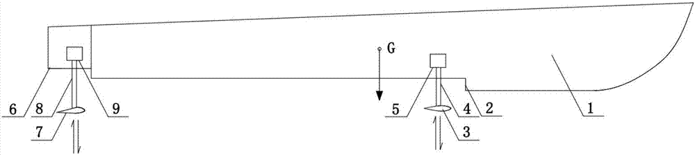
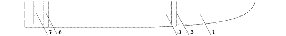
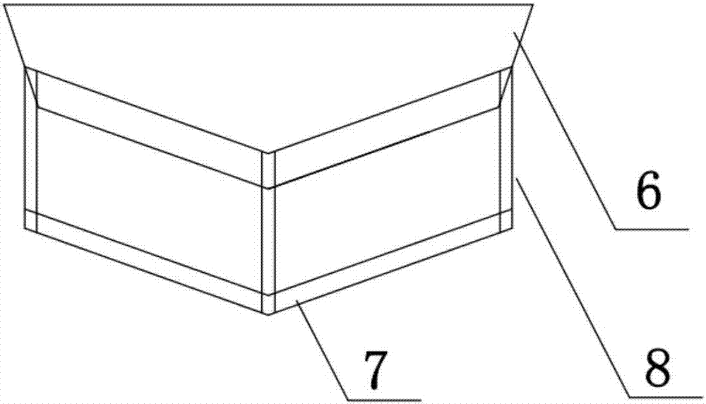
[0027] See Figure 1-Figure 9 , the present invention comprises a hull 1 (comprising a monohull or a catamaran), a false tail 6, a step 2 arranged at the bottom of the front body in the hull 1, a front hydrofoil 3 installed behind the step 2 through a front pillar 4, and the front The hydrofoil 3 and the front prop 4 are controlled by the front retractable device 5 to realize the retraction and release of the front hydrofoil, the rear hydrofoil 7 is installed under the false tail 6 through the rear prop 8, and the rear hydrofoil 7 and the rear prop 8 are retracted by the rear The unfolding device 9 is controlled to realize the retracting and releasing of the rear hydrofoil, and the front retracting device 5 and the rear retracting device 9 are installed inside the hull.

[0028] The mode of operation of the present invention is as follows...


PUM


Abstract

The invention provides a step composite ship form with retractable type hydrofoils. The step composite ship comprises a hull with a step and a fake tail, a front hydrofoil, a rear hydrofoil, supporting columns of the hydrofoils and devices for separately controlling the corresponding hydrofoil to extend/retract, wherein the front hydrofoil is located behind the step; the rear hydrofoil is located under the fake tail; the hydrofoil extending and retracting devices are arranged in the hull, and are used for extending/retracting the front hydrofoil and the rear hydrofoil; and when being unfolded, the hydrofoils are located under a baseline of the hull; and when the hydrofoils are retracted, the front hydrofoil is located behind the step, and the rear hydrofoil is located under the fake tail, and the front hydrofoil and the rear hydrofoil are close to the bottom of the hull. According to the step composite ship form with the hydrofoils which are additionally arranged disclosed by the invention, in an abyssal region, excellent hydrodynamic characteristics of the hydrofoils can be utilized to achieve the purposes of reducing resistance, increasing speed and saving energy, and the vertical damp of the hydrofoils and the longitudinal self-stability characteristic of a hydrofoil system can also be utilized to notably improve the movement performance of a ship and light boat; and in a shallow water region, after the front hydrofoil is retracted to the step, the rear hydrofoil can be retracted under the fake tail, so that the situation that the normal exerting of the functions of the ship and the light boat is influenced because the hydrofoils touch the ground is avoided.

Description

technical field [0001] The invention relates to the field of composite high-performance ships, in particular to the hydrodynamic configuration of stepped composite ships with retractable hydrofoils. Background technique [0002] Reducing drag and increasing speed is the consistent pursuit of ship designers. Today, with high oil prices and limited greenhouse gas emissions, drag reduction and energy saving have also become a hot spot in the shipbuilding industry. As a hydrodynamic component with high efficiency ratio, hydrofoil is frequently used on high-speed ships. [0003] A hydrofoil is a wing that works in water. It moves in the water just like an airplane wing moves in the air to generate lift. There are many benefits brought by hydrofoils. Since the density of water is about 800 times that of air, under the same lift force, the scale of hydrofoils is much smaller than that of airfoils. After adding hydrofoils, the high-speed boats that rely on the lift of the hydrofo...

Claims


Application Information

Patent Timeline
Patent Type & Authority Applications(China)
IPC IPC(8): B63B1/30
CPCB63B1/30B63B2001/202
Inventor 何术龙眭爱国马丹萍
Owner CHINA SHIP SCIENTIFIC RESEARCH CENTER (THE 702 INSTITUTE OF CHINA SHIPBUILDING INDUSTRY CORPORATION)
Why Eureka
Try Eureka