Valve assembly cleaning device

a valve assembly and cleaning device technology, applied in the direction of machines/engines, mechanical equipment, cleaning using liquids, etc., can solve the problems of limited propane flow to the engine, and the replacement of the valve assembly at substantial cost, and achieve the effect of restricting the flow of propane to the engin

Inactive Publication Date: 2007-06-19
STEDAM MACK L
View PDF10 Cites 7 Cited by
  • Summary
  • Abstract
  • Description
  • Claims
  • Application Information

AI Technical Summary

Benefits of technology

[0006]An object of the present invention is to provide a new valve assembly cleaning device which cleans the inner components of a liquid propane regulator and lock-off valve assembly. The valve assembly is typically positioned between a propane burning engine and a propane tank. Generally, liquid propane from the propane tank becomes a gas as it travels through the valve assembly. As this happens, a chemical reaction takes place which deposits propylene on inner components of the valve assembly. As the propylene builds on the components, flow of the propane to the engine is restricted. When the flow is restricted to such a degree that it affects the operation of the engine, the valve assembly is replaced at substantial cost. It has been found that conventional carburetor cleaning fluid may be drawn through the valve assembly without harming the engine. The cleaning fluid removed the propylene from the components so that the valve assembly operates correctly and does not require replacement.

Problems solved by technology

As the propylene builds on the components, flow of the propane to the engine is restricted.
When the flow is restricted to such a degree that it affects the operation of the engine, the valve assembly is replaced at substantial cost.

Method used


Image

  • Valve assembly cleaning device
  • Valve assembly cleaning device

Examples


Embodiment Construction

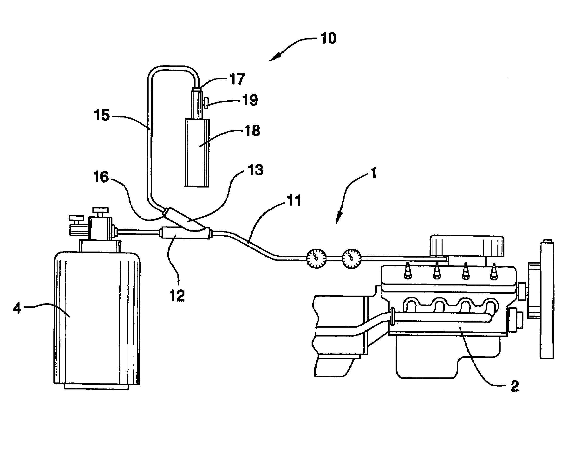
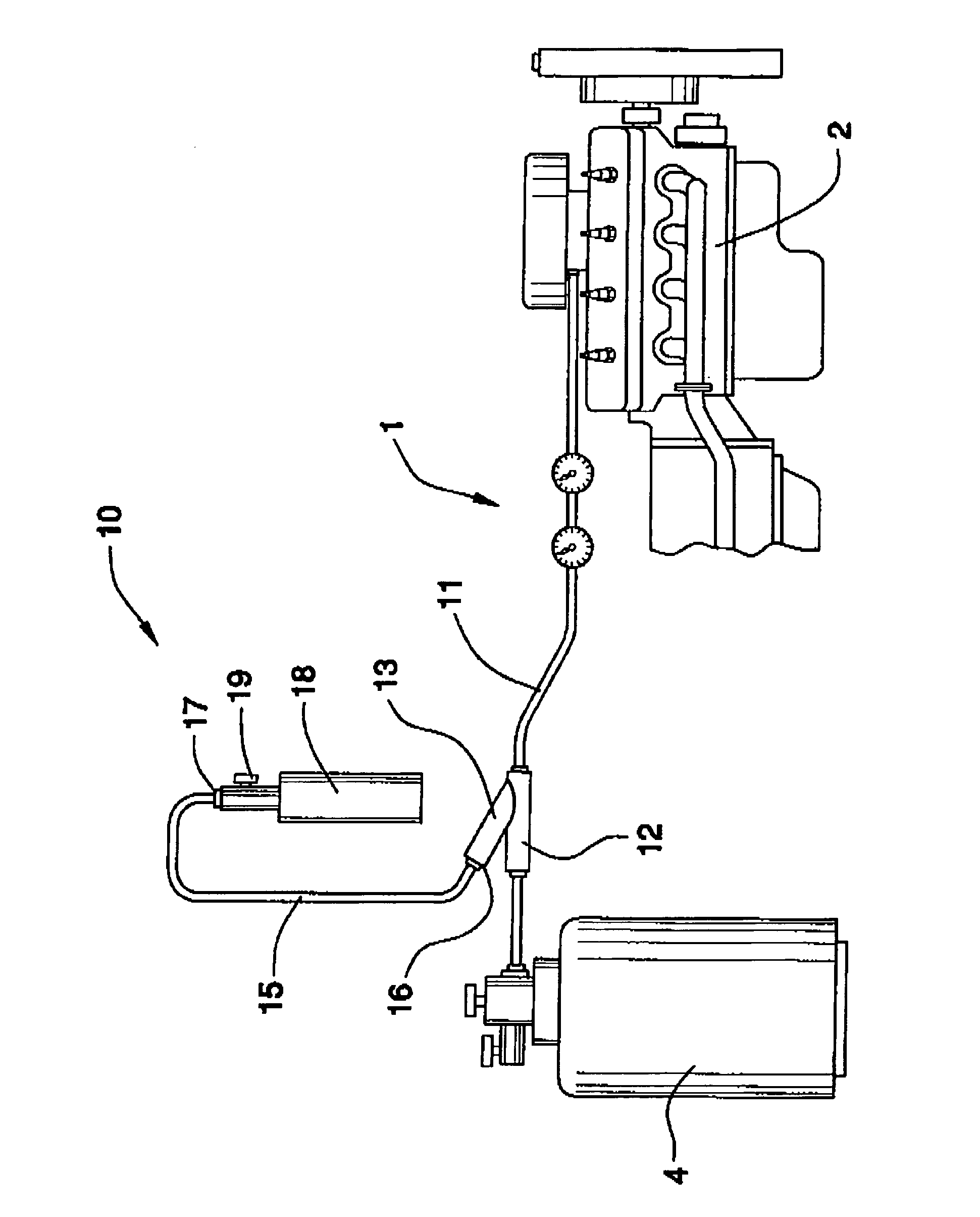
[0012]With reference now to the FIGURE, a new engine cleaning systems embodying the principles and concepts of the present invention and generally designated by the reference numeral 10 will be described.

[0013]As best illustrated in the FIGURE, the valve assembly cleaning device 10 generally comprises a device for cleaning the liquid propane regulator and lock-off valve assembly 1 that is positioned between a propane burning engine 2 and a propane tank 4. A conduit 11 fluidly couples the liquid propane regulator and lock-off valve assembly 1 to a propane tank 4. The cleaning system includes a first tube 12 selectively coupled to the conduit 11 such that the first tube 12 is in fluid connection with the conduit 11 and propane flows from the propane tank 4 to the assembly flows through the first tube 12. The conduit 11 replaces a coupler, not shown, which conventionally couples sections of the conduit 11 together.

[0014]An inlet 13 is fluidly coupled to and extends away from the first ...


PUM


Abstract

A valve assembly cleaning device includes a conduit fluidly couples the liquid propane regulator and valve assembly to a propane tank. The cleaning system includes a first tube selectively coupled to the conduit such that the first tube is in fluid connection with the conduit and propane may flow from the propane tank to the assembly flows through the first tube. A container has a valve cleaning fluid therein. The container is in fluid communication with the first tube. Cleaning fluid may enter the conduit such that the valve assembly is cleaned by the cleaning fluid.

Description

BACKGROUND OF THE INVENTION[0001]1. Field of the Invention[0002]The present invention relates to engine cleaning systems and more particularly pertains to a new engine cleaning systems for effectively cleaning the needles, seats, and other internal components found in regulators for liquid propane engines.[0003]2. Description of the Prior Art[0004]The use of engine cleaning systems is known in the prior art. U.S. Pat. No. 5,271,361 describes an engine conditioning apparatus and method for cleaning carbon deposits and related residue and contaminants from fuel ports and internal surfaces of an internal combustion engine fuel system. Another type of engine cleaning system is U.S. Pat. No. 5,287,834 describes a method and apparatus for removing internal deposits and contaminants from fuel injected and carbureted internal combustion engines. U.S. Pat. No. 5,055,210 describes a cleaning and lubricating composition for mechanical seals prolonging their life.[0005]While these devices fulfi...

Claims


Application Information

Patent Timeline
Patent Type & Authority Patents(United States)
IPC IPC(8): B08B7/04B08B3/00B08B9/00F02B3/06F02B43/00F02M21/02
CPCB08B9/00F02B77/04F02M21/0212F02M21/0227Y02T10/32Y02T10/30
Inventor STEDAM, MACK L.
Owner STEDAM MACK L
Why Eureka
Try Eureka