Investment casting mold design and method for investment casting using the same

a technology of investment casting and mold design, applied in the field of mold design, can solve the problems of large ceramic dust, design variation, and design not allowing bottom feeding of the cavity of the par

Active Publication Date: 2007-06-19
RTX CORP
View PDF1 Cites 79 Cited by
  • Summary
  • Abstract
  • Description
  • Claims
  • Application Information

AI Technical Summary

Benefits of technology

[0009]In accordance with the present disclosure, a method for investment casting broadly comprises positioning a base plate relative to a die; molding a first material between the die and at least a first surface portion of the base plate; securing one or more patterns to the base plate, the one or more patterns comprising a second material; applying one or more coating layers over at least portions of the one or more patterns and at least a portion of the first material; substantially removing the first material through an interior receptacle of a manifold body and the second material through an exterior receptacle of the manifold body to leave one or more shells formed by the coating layers; removing said base plate; introducing molten metal to the one or more shells through the interior receptacle of the manifold body; permitting the molten metal to solidify; and destructively removing one or more investment casting molds.

Problems solved by technology

However, the trimming process liberates a large amount of ceramic dust.
This ceramic dust poses a hazard as the dust could become lodged within the molds and trapped in the thin features being produced in the molded part, thus causing part variations.
However, the mold design does not permit bottom feeding the part cavity and also fails to leave a passage for wax to evacuate during the venting or dewax process.

Method used


Image

  • Investment casting mold design and method for investment casting using the same
  • Investment casting mold design and method for investment casting using the same
  • Investment casting mold design and method for investment casting using the same

Examples


Embodiment Construction

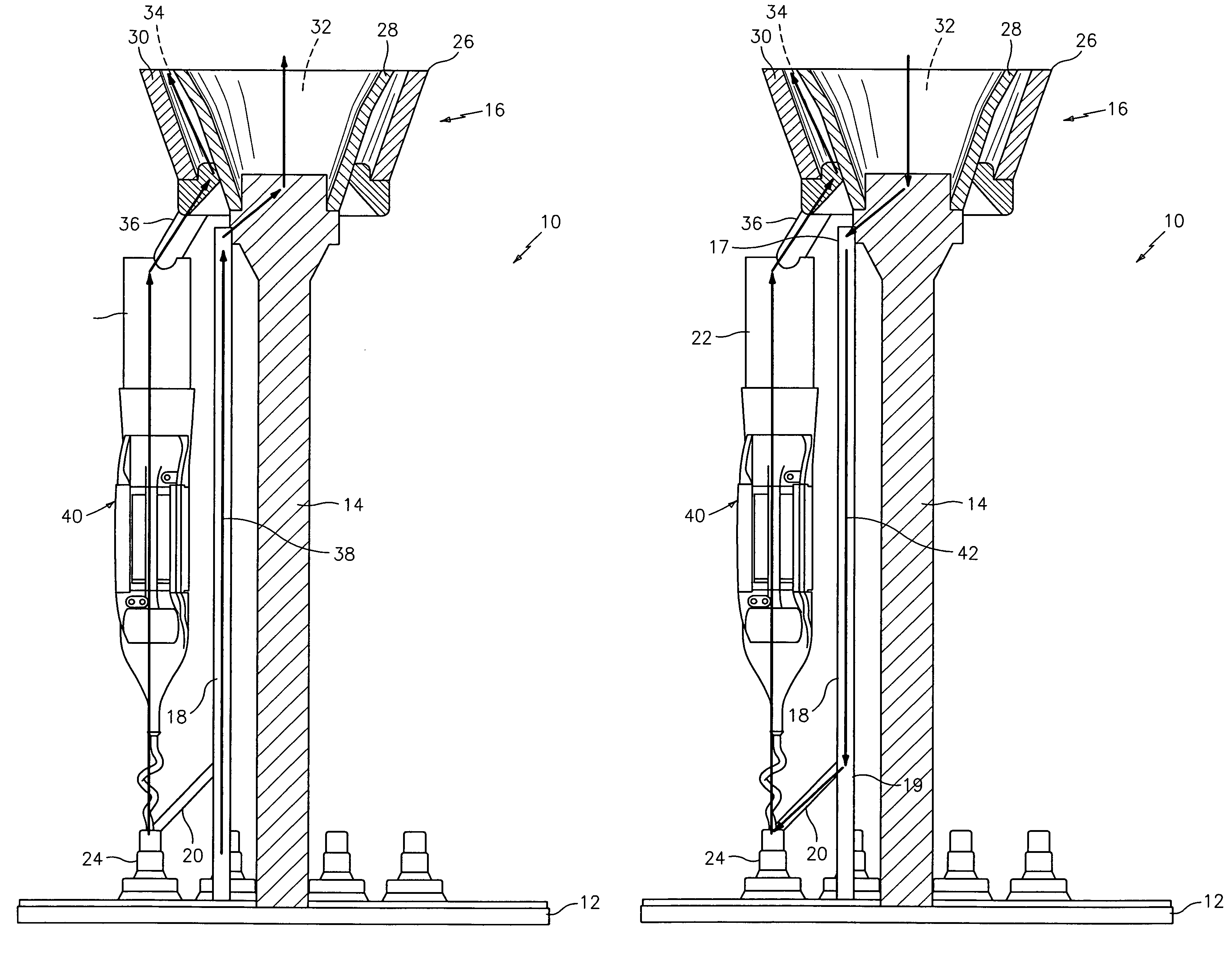
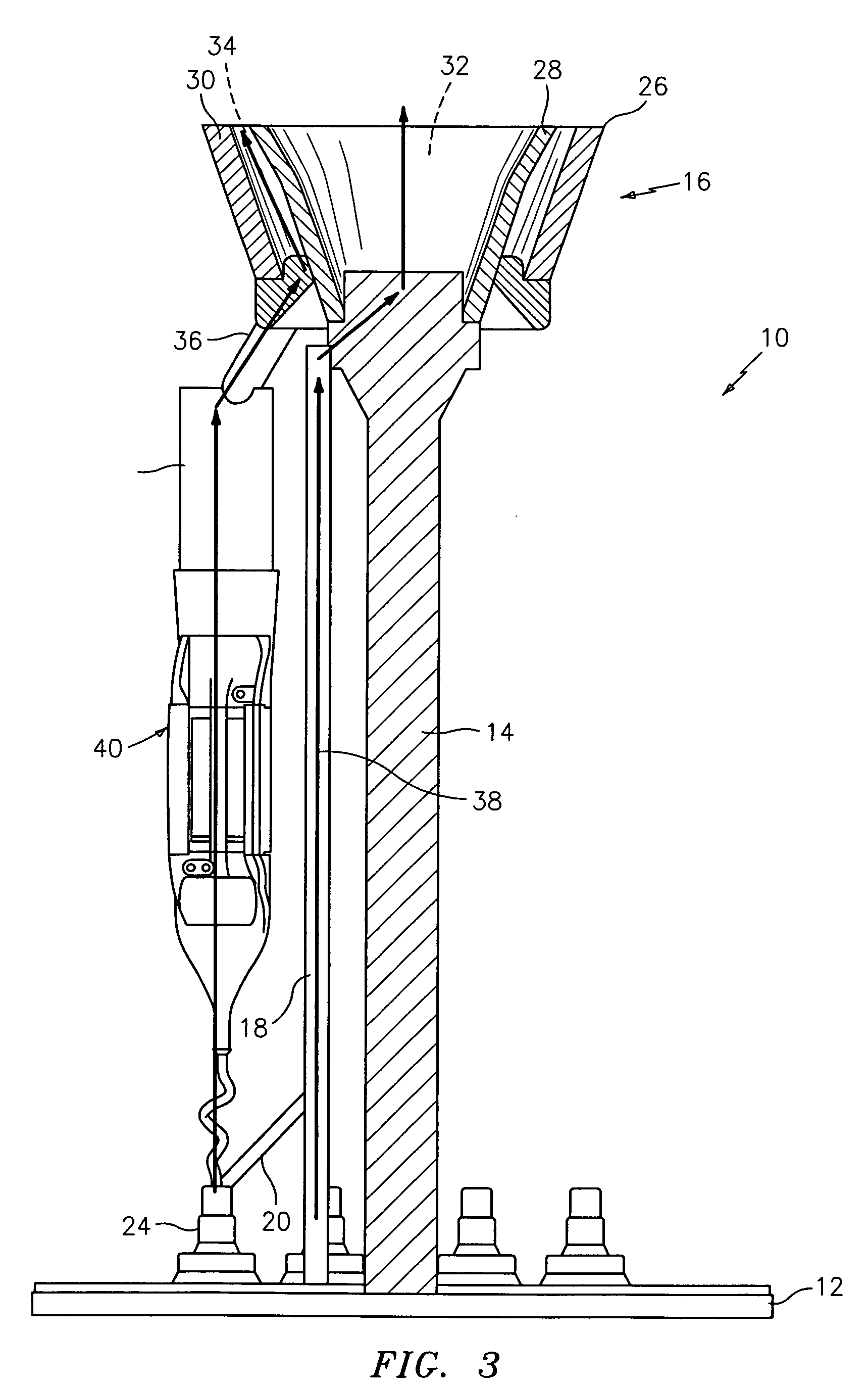
[0017]The investment casting mold design and method for investment casting using the same described herein combines the advantages of both prior art designs. The investment casting mold design utilizes a manifold body equipped with a dual wall pour cup and a single baseplate which eliminates the need for trimming the top plate and provides a route for wax material to exit during the dewax process. In addition, the mold can be shelled and prepped for casting in a shorter period of time, which limits the amount of shell which must be trimmed away from the pour cup and the amount of debris that could potentially enter the mold.

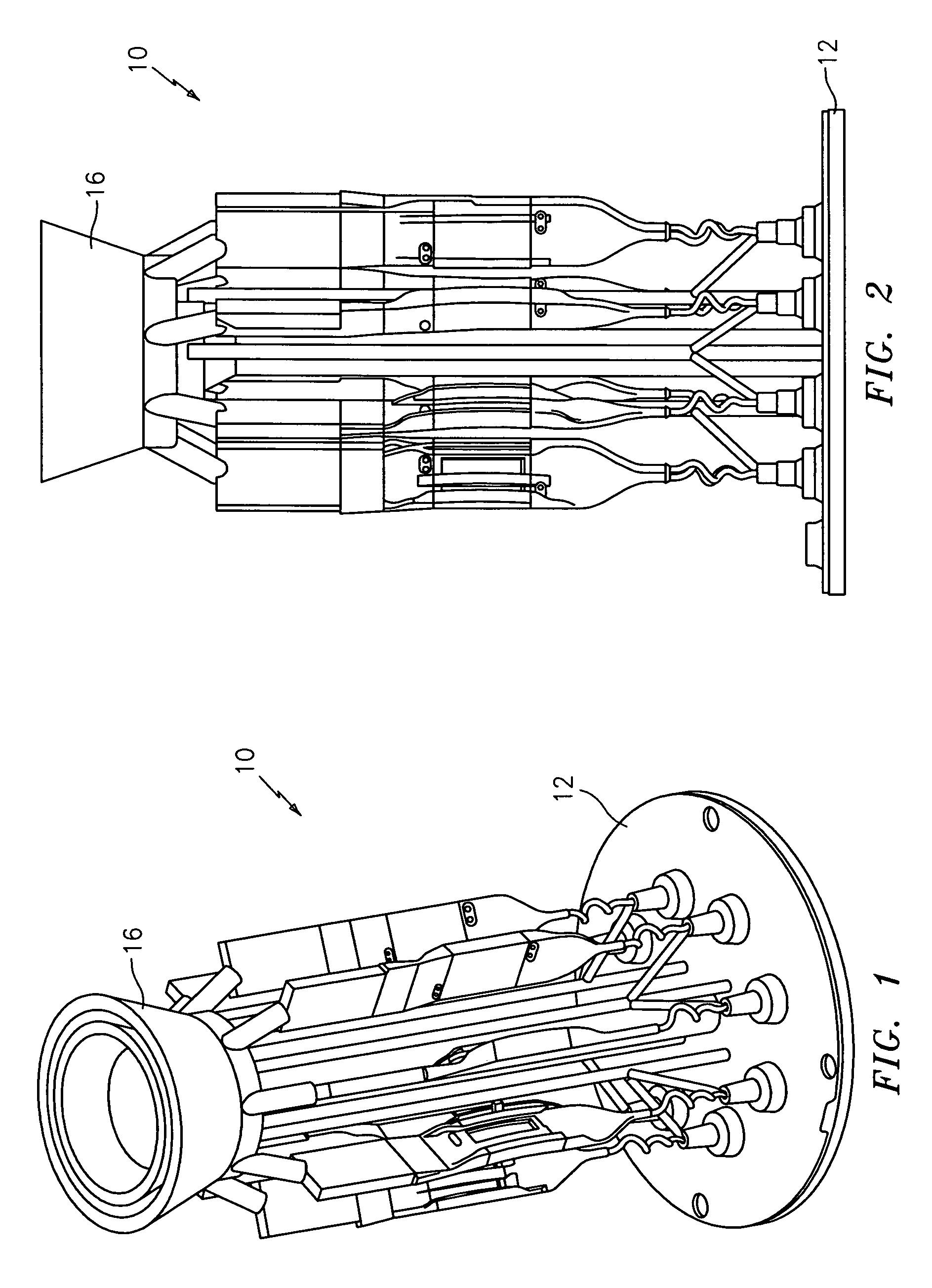
[0018]Referring generally now to FIGS. 1–2, the investment casting mold design of the present disclosure is shown. An investment casting mold design 10 may generally comprise a baseplate 12 that supports a sprue 14 upon which a manifold body 16 is mounted. One or more feeder conduits 18 may be connected to the sprue 14. Each feeder conduit 18 may be in communicat...


PUM

PropertyMeasurementUnit
shapeaaaaaaaaaa
crystal orientationaaaaaaaaaa
erosionaaaaaaaaaa

Abstract

A method for investment casting includes the steps of positioning a base plate relative to a die; molding a first material between the die and at least a first surface portion of the base plate; securing one or more patterns to the base plate, the one or more patterns comprising a second material; applying one or more coating layers over at least portions of the one or more patterns and at least a portion of the first material; substantially removing the first material through an interior receptacle of a manifold body and the second material through an exterior receptacle of the manifold body to leave one or more shells formed by the coating layers; removing said base plate; introducing molten metal to the one or more shells through the interior receptacle of the manifold body; permitting the molten metal to solidify; and destructively removing one or more investment casting molds.

Description

FIELD OF USE[0001]The present disclosure relates to mold designs and, more particularly, to investment casting mold designs.BACKGROUND OF THE INVENTION[0002]Investment casting is a commonly used technique for forming metallic components having complex geometries, especially hollow components, and is used in the fabrication of superalloy gas turbine engine components.[0003]A well developed field exists regarding the investment casting of turbine engine parts such as blades and vanes. In an exemplary process, a mold is prepared having one or more mold cavities, each having a shape generally corresponding to the part to be cast. An exemplary process for preparing the mold involves the use of one or more wax patterns of the part. The patterns are formed by molding wax over ceramic cores generally corresponding to positives of the cooling passages within the parts. The patterns are mounted to a shelling fixture. Prior to mounting, the fixture may be prepared to receive the patterns. For ...

Claims


Application Information

Patent Timeline
Patent Type & Authority Patents(United States)
IPC IPC(8): B22C9/04
CPCB22C9/043B22C9/082B22C7/02B22D23/06
Inventor BULLIED, STEVEN J.REILLY, P. BRENNAN
Owner RTX CORP
Why Eureka
Try Eureka