Gripping insert and method of gripping a tubular

a tubular insert and insert technology, applied in the direction of manufacturing tools, sealing/packing, borehole/well accessories, etc., can solve the problems of increasing surface corrosion, affecting the effect of corresponding gripping elements, and requiring considerable clamping or gripping forces to transmit torqu

Active Publication Date: 2007-06-19
WEATHERFORD TECH HLDG LLC
View PDF65 Cites 51 Cited by
  • Summary
  • Abstract
  • Description
  • Claims
  • Application Information

AI Technical Summary

Problems solved by technology

In particular, for rotation of the object, considerable clamping or gripping forces are necessary to transmit torque.
However, if these inserts are used for rotating the object, it is possible that the corresponding gripping elements may tilt away under heavy load produced while transmitting torque to the object.
Moreover, such inserts can cause undesired indentations or markings on the surface of the object to be clamped such that this surface undergoes increased corrosion.
Prior art gripping apparatuses cause scarring and / or marking of the object being grippingly engaged when imparting torque to the object.
The scarring and / or marking increases damage to the object, thus possibly impairing the effectiveness of the object in the well operations and increasing the incidence of failure of the pipe, e.g., casing or other tubular body, within the wellbore.
Additionally, the scarring and / or marking may increase corrosion along the pipe's surfaces.

Method used


Image

  • Gripping insert and method of gripping a tubular
  • Gripping insert and method of gripping a tubular
  • Gripping insert and method of gripping a tubular

Examples


first embodiment

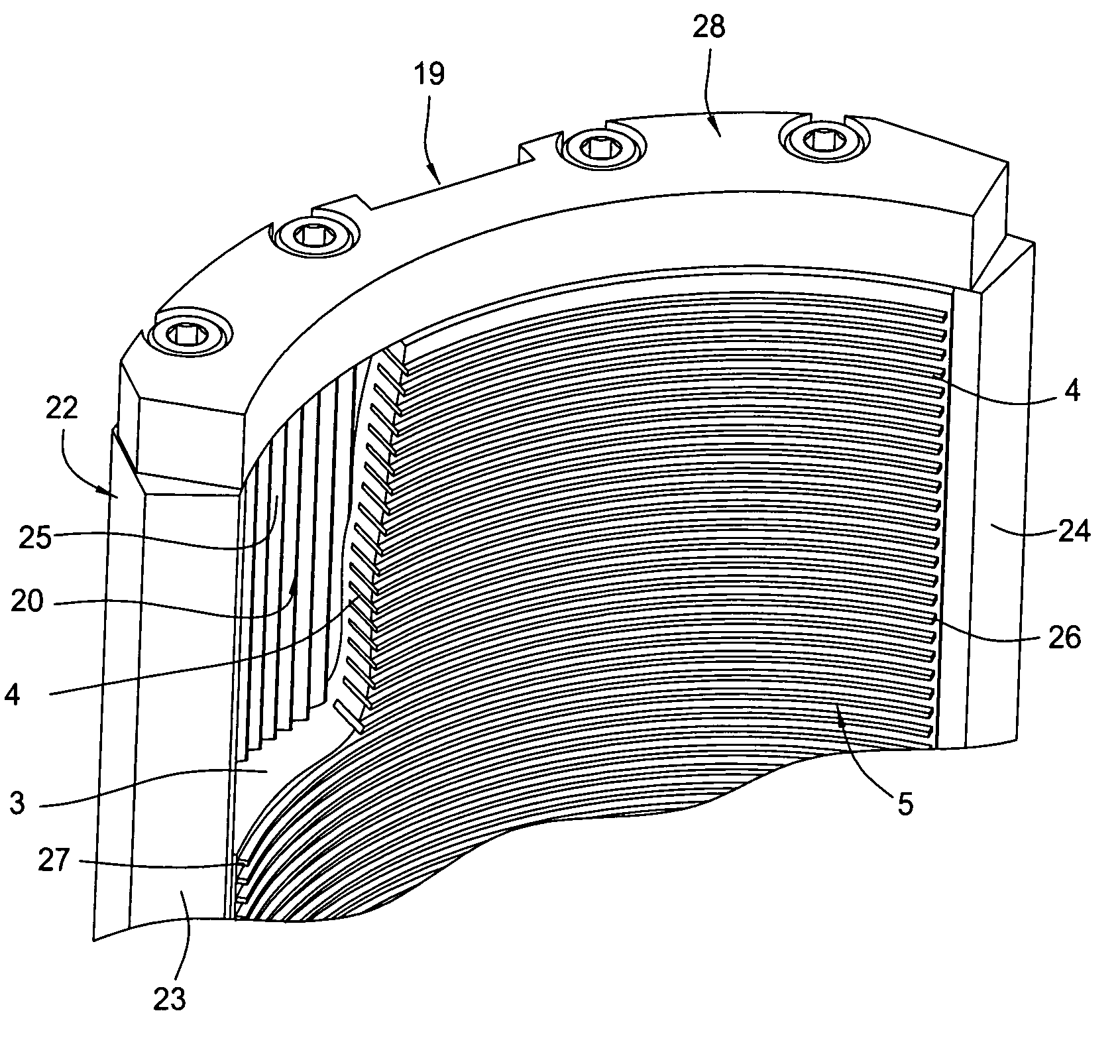
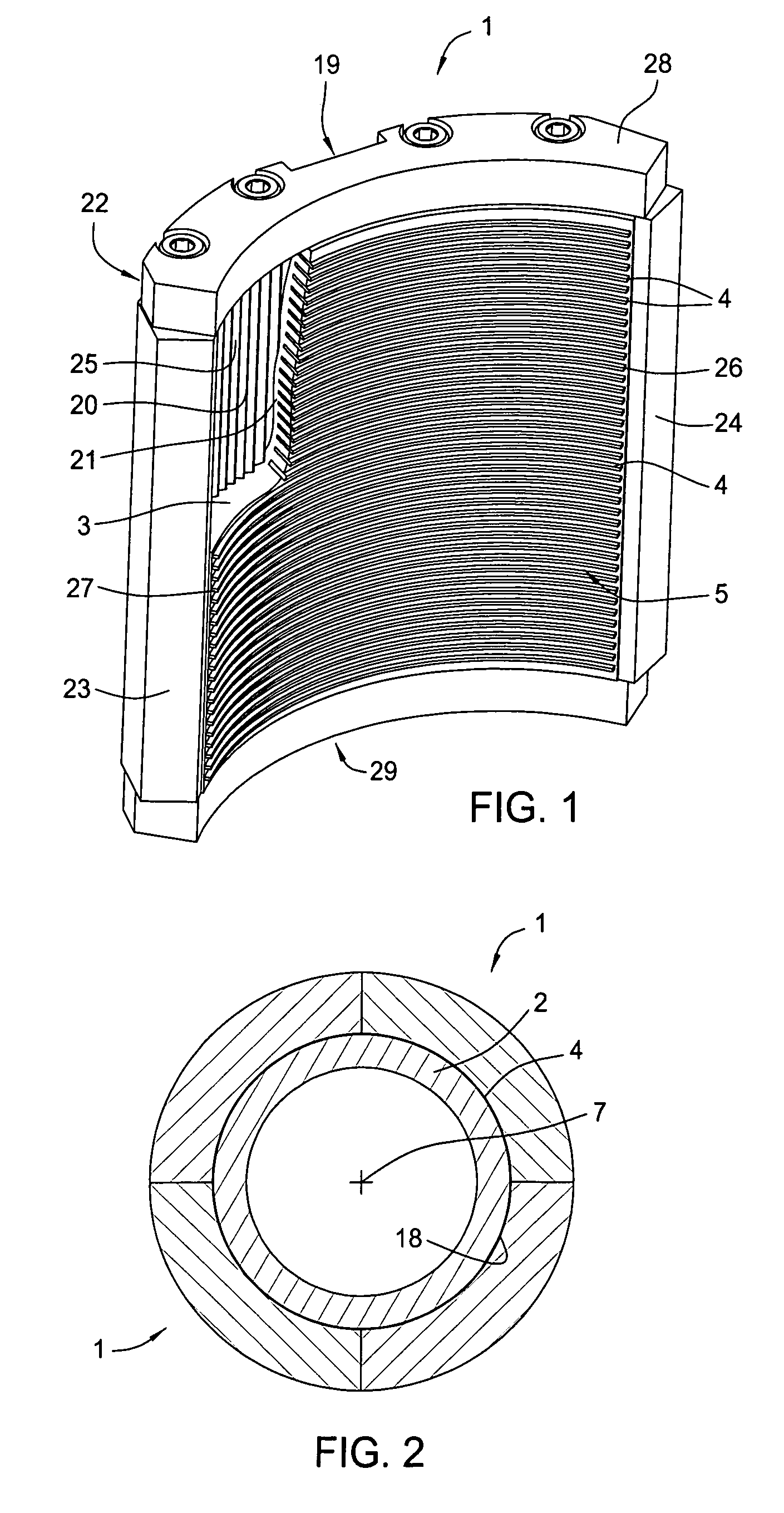
[0034]FIG. 1 is a side elevational view of an insert 1. FIG. 2 is a downward cross-sectional view of four inserts 1 arranged around a tubular object. The insert 1 is configured to apply frictional force against a corresponding moveable object, such as the tubular object 2 in FIG. 2. The insert 1 is designed to operate within a jaw of a clamping device or gripping apparatus (not shown), such as a tong, spider, gripping head, or elevator. One or more inserts 1 as shown in FIG. 1 are utilized around the object 2 in connection with a gripping apparatus. When using multiple inserts 1, the inserts 1 are preferably arranged in a circular manner to surround the object 2, and the inserts 1 may be stacked upon one another as desired. The different inserts 1 may be arranged within an adaptor or the like with two or more of these inserts 1 arranged around the object 2 and with as many of such groups of two or more inserts 1 stacked above each other as necessary. For example, four inserts 1 may ...

second embodiment

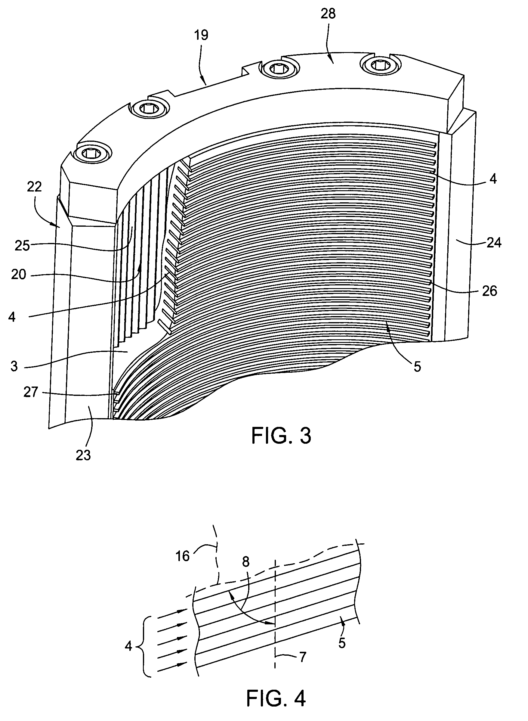
[0041]In FIG. 4, the invention is illustrated. In this embodiment, the gripping elements 4 are arranged at an angle 8 different than 90° with respect to longitudinal axis 7 of the insert 1. The angle 8 may be in the range of, for example, about 50° to 130°, about 70° to 110°, or about 85° to 95°.

[0042]In another embodiment of a gripping element, shown by the dotted line in FIG. 4 at “16,” the gripping element may have a wave-like curvature such that the gripping element 16 is substantially sinusoidal in lengthwise direction 17.

[0043]FIGS. 5 to 7 illustrate different embodiments of the gripping element 4. In FIGS. 5 and 6A, teeth 11, 12 are used as gripping elements 9, while in FIG. 7, grains or particles 10 are used as gripping elements 9. In FIG. 5, a top view of a gripping element 30 is shown. In this arrangement, the gripping element is not curved, as in other embodiments, but is essentially linear. Alternatively, the gripping element 30 may represent an arcuate gripping element ...


PUM


Abstract

The present invention generally provides an insert for a clamping device or gripping apparatus for conducting translational forces and / or torque into a moveable object, such as a tubular, casing, liner, pipe, expandable tubular, tubing, drill pipe. In one aspect, the insert comprises a base material and a plurality of gripping elements forming an object gripping surface. Gripping elements are at least partially embedded in the base material. The gripping elements in one embodiment are curved to correspond to an outer circumference of an object to be gripped. In one embodiment, the gripping elements are inclined relative to a longitudinal axis of the insert. In another aspect, the gripping elements may comprise grains or particles of a hardened or super-hard material. The present invention also provides a method of making the insert and using the insert in a gripping apparatus.

Description

CROSS-REFERENCE TO RELATED APPLICATIONS[0001]This application claims benefit of U.S. Provisional Patent Application Ser. No. 60 / 450,426 entitled “Insert for Clamping Device”, filed Feb. 27, 2003, which application is herein incorporated by reference in its entirety. This application further claims benefit of U.S. Provisional Patent Application Ser. No. 60 / 490,555 entitled “Insert for Gripping Apparatus”, filed Jul. 28, 2003, which application is herein incorporated by reference in its entirety.BACKGROUND OF THE INVENTION[0002]1. Field of the Invention[0003]Embodiments of the invention relate to an insert for a clamping device or gripping apparatus, which is used in particular in the field of oil and gas exploration, wherein such a clamping device or gripping apparatus conducts translational forces and / or torques into a moveable object. Such a moveable object can be a tubular body, including casing, drill pipe, etc. Lengths or stands are added to or detached from such casing or drill...

Claims


Application Information

Patent Timeline
Patent Type & Authority Patents(United States)
IPC IPC(8): E21B19/10B25B13/50E21B19/07E21B19/16
CPCB25B13/5016E21B19/07E21B19/16B25B1/24F16L3/10
Inventor JAENSCH, MANFRED
Owner WEATHERFORD TECH HLDG LLC
Why Eureka
Try Eureka