
Fire shield method

a fire shield and shield technology, applied in the field of fire shields, can solve the problems of adding unwanted weight and cost, and use of such materials is typically unsuitable for fire protection, and achieve the effect of improving fire protection

Inactive Publication Date: 2007-06-19
PRATT & WHITNEY CANADA CORP
View PDF15 Cites 33 Cited by
  • Summary
  • Abstract
  • Description
  • Claims
  • Application Information

AI Technical Summary

Benefits of technology

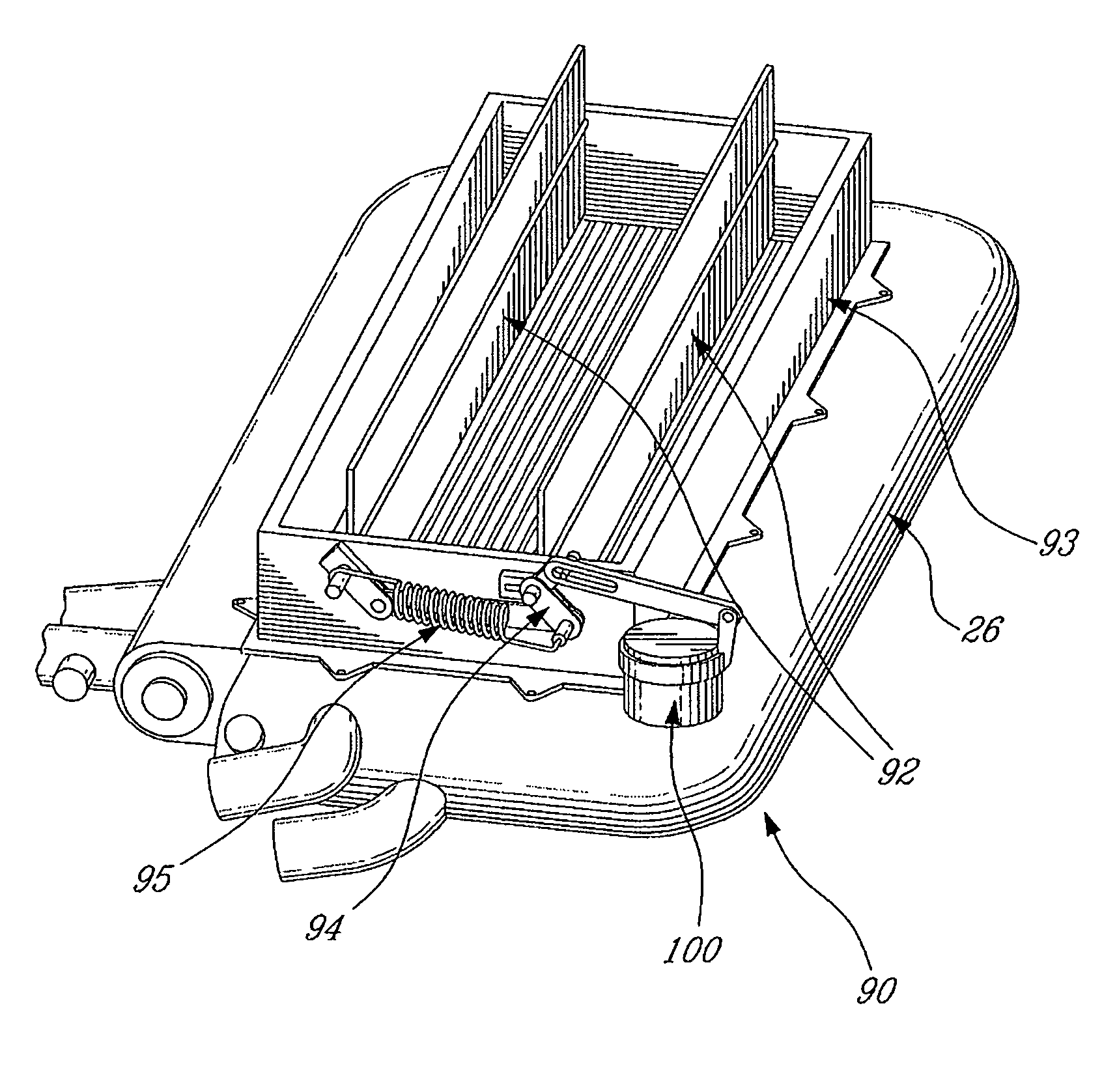
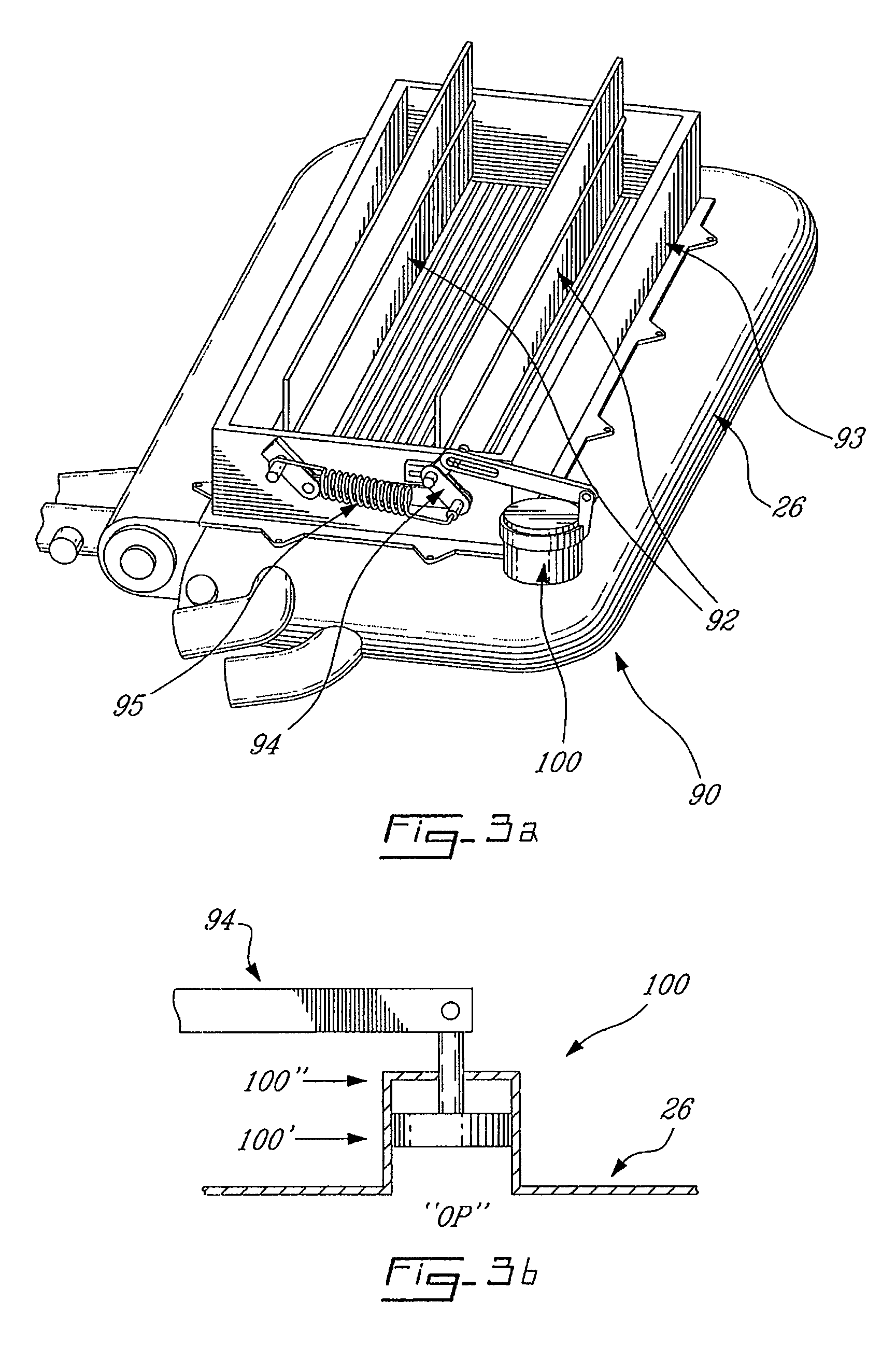
[0004]The present application is aimed at providing improved fire protection for heat exchanger and other onboard equipment having matrix surface(s) within an aircraft fire zone which may be exposed to direct flame impingement in case of a fire event. This therefore allows the use of non-fire proof materials, if desired.

Problems solved by technology

The use of fireproof or fire-resistant materials is often proposed for use in fire risk areas such as oil coolers and heat exchangers containing flammable fluids (such as fuel), however the use of such materials typically adds unwanted weight and cost.

Method used


Image

  • Fire shield method
  • Fire shield method
  • Fire shield method

Examples


Embodiment Construction

[0013]The present invention will now be described with reference to the fire protection of an oil cooler for an aircraft auxiliary power unit (APU), however it will be understood that the invention is applicable to other aircraft heat exchangers using air as the cooling medium, and particularly those used to cool onboard flammable fluids. The present invention is related to co-pending patent application Ser. No. 10 / 370,803 filed 20 Feb. 2003, commonly assigned herewith, and the contents of that application are incorporated herein by this reference.

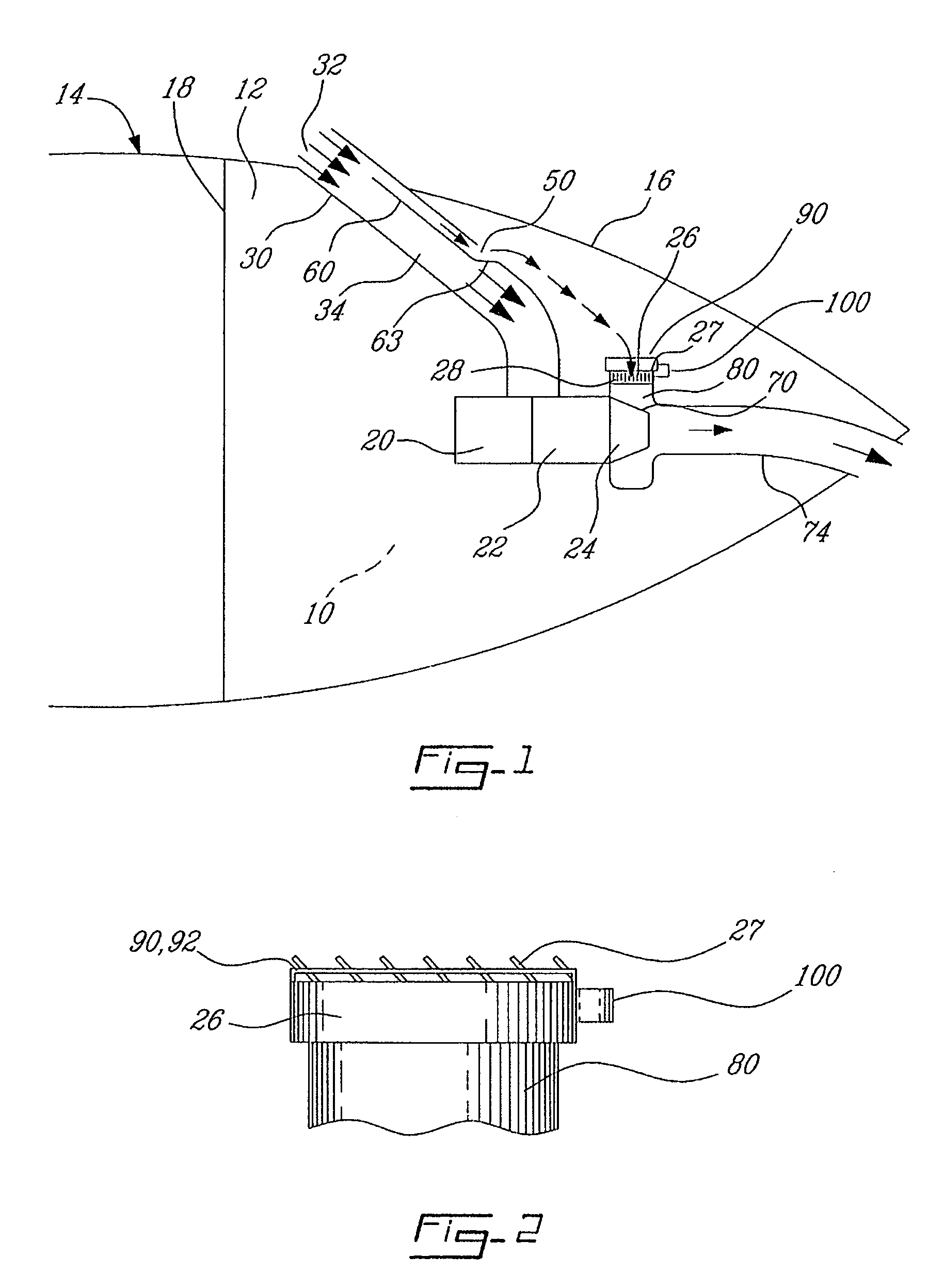
[0014]FIG. 1 schematically illustrates a passive cooling system for an auxiliary power unit 10. Auxiliary power unit 10 is positioned in a compartment 12, which is located in the aft fuselage of an aircraft 14 having an exterior surface 16. Compartment 12 is separated from the rest of the fuselage by a firewall 18, and exterior surfaces 16 of aircraft 14 form the remaining walls of compartment 12. Auxiliary power unit 10 typically includes...


PUM


Abstract

Provided is a method for providing fire shield protection to an aircraft auxiliary power unit, or portion thereof, or to other aircraft systems.

Description

CROSS-REFERENCE TO RELATED APPLICATIONS[0001]This application is a divisional of U.S. patent application Ser. No. 10 / 737,769 filed Dec. 18, 2003 now U.S. Pat. No. 7,040,576, the entire specification of which is incorporated by reference herein.FIELD OF THE INVENTION[0002]The present invention relations to the provision of fire protection and, more particularly, to a body containing a pressurised fluid.BACKGROUND OF THE ART[0003]Although in-flight occurrences of fire are rare, both prudence and government regulation dictate that fire protection be provided onboard aircraft. Onboard fire protection measures should ideally be not only effective but also lightweight, extremely reliable, low maintenance and low cost, among other things. The use of fireproof or fire-resistant materials is often proposed for use in fire risk areas such as oil coolers and heat exchangers containing flammable fluids (such as fuel), however the use of such materials typically adds unwanted weight and cost. No...

Claims


Application Information

Patent Timeline
Patent Type & Authority Patents(United States)
IPC IPC(8): B64C1/10A62C2/14A62C3/08A62C8/08B64D33/10B64D45/00B64D47/00F02C7/25
CPCA62C2/14B64D33/10F02C7/25A62C3/08F05D2220/50
Inventor NOISEUX, NOELBERNARD, MARTINWHITING, MICHAEL OWEN
Owner PRATT & WHITNEY CANADA CORP
Learn More