Method of uniformly fixing toner to recording medium in image forming apparatus

a technology of image forming apparatus and uniform fixing, which is applied in the direction of electrographic process, instrument, and semiconductor/solid-state device details, etc., can solve the problems of easy deformation of toner image, deterioration of image quality, and defective fixing of portions

Inactive Publication Date: 2007-06-19
RICOH KK
View PDF20 Cites 51 Cited by
  • Summary
  • Abstract
  • Description
  • Claims
  • Application Information

AI Technical Summary

Problems solved by technology

Therefore, although at least a part of toner particles are integrated by binding, the toner image tends to get deformed easily.
As a result, there is a big difference in an area of each toner after pressurizing and fixing, resulting in unevenness of graininess and gloss, thereby deteriorating an image quality.
Further, since heat cannot be transmitted easily to the toner in the recesses, that portion tends to have defective fixing.
As a result, at a time of fixing, height of toner is changed by 40% to 80% and the area of each toner does not become even due to irregularities on the surface of the recording medium, leading to the deterioration of the image quality.
The difference in the area of each toner due to the irregularities on the surface of the paper, as shown by the widths W1 and W2, leads to a deterioration of the graininess of a half-tone image, particularly in a case of a color image.
Moreover, that causes a difference in glossiness of the toner image in an area of the recesses and the bulges, resulting in unevenness in gloss, thereby deteriorating the image quality.
Therefore, in a portion such as a low density portion where an amount of integrated toner is less, sometimes the toner could not be transferred completely to the recording medium.
As a result of this, the image quality is deteriorated.

Method used


Image

  • Method of uniformly fixing toner to recording medium in image forming apparatus
  • Method of uniformly fixing toner to recording medium in image forming apparatus
  • Method of uniformly fixing toner to recording medium in image forming apparatus

Examples


first embodiment

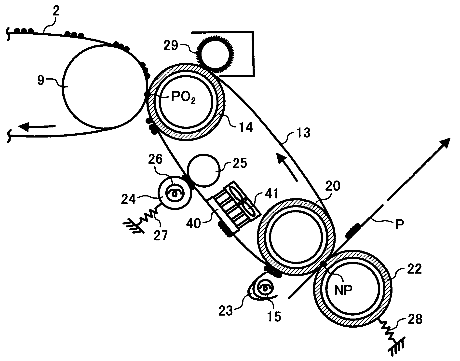
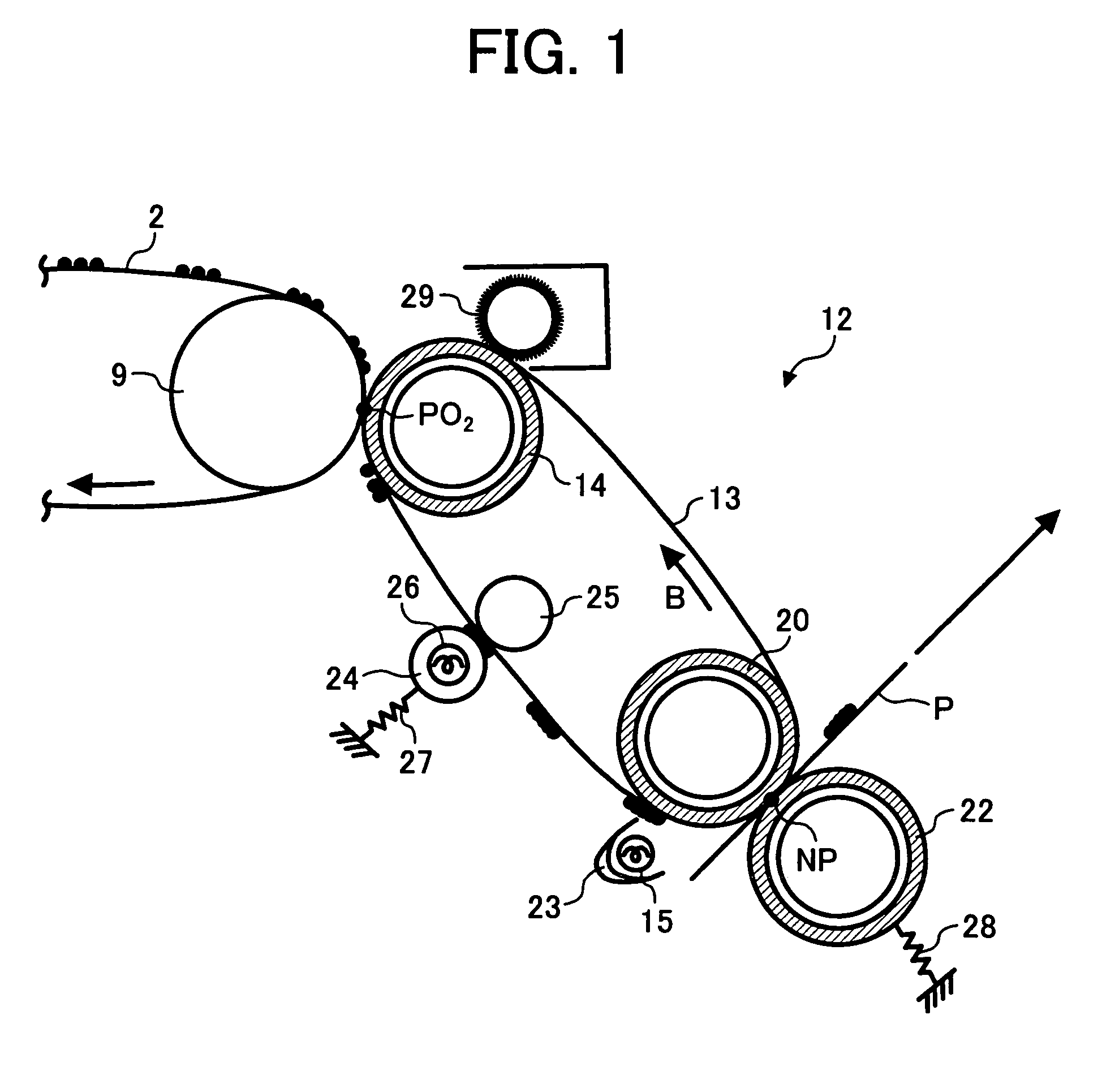
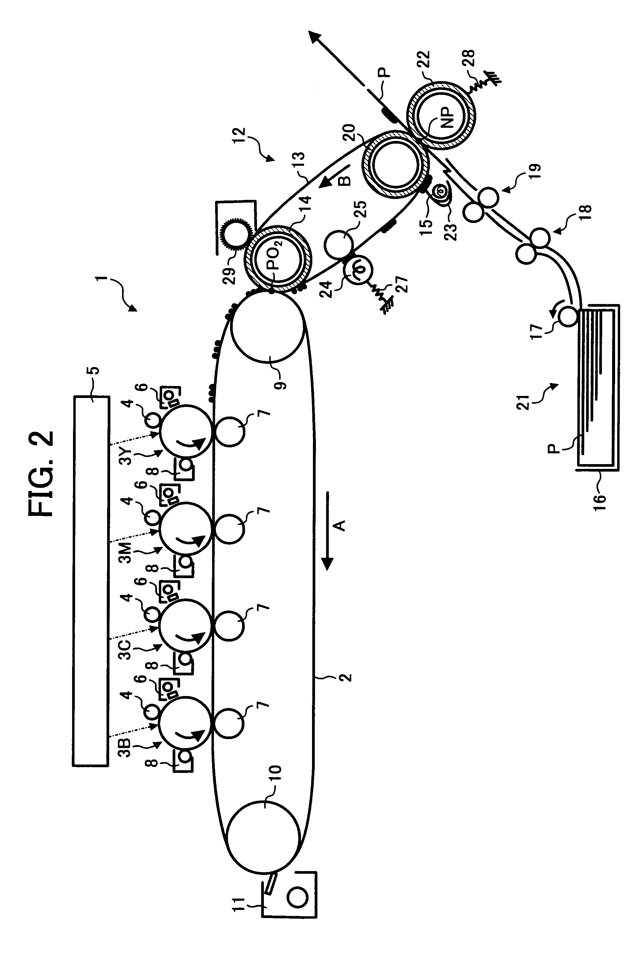
[0032]FIG. 1 is a schematic diagram of an image transferring and fixing device according to the present invention. FIG. 2 is a schematic diagram of a main part of an image forming apparatus provided with the image transferring and fixing device, in concrete terms, a tandem color copying machine. The tandem color copying machine shown in FIG. 2 includes an image forming section 1 at a center of the machine, a paper feeding section 21 beneath the image forming section 1, and an image reading section that is not shown, above the image forming section 1.

[0033]The image forming section 1 includes an intermediate transfer belt 2, a drive roller 9, and a driven roller 10. The intermediate transfer belt 2 has a transferring surface that extends in a horizontal direction. The intermediate transfer belt is stretched over the drive roller 9 and the driven roller 10 and is rotatable in a direction of an arrow A. Photosensitive drums (image carriers) 3Y, 3M, 3C, and 3B (hereinafter, “photosensit...

second embodiment

[0074] the fixing-assisting agent is applied to the toner image that is integrated on the transferring and fixing belt 13 by the applying roller 32. Therefore, as compared to a case in which the fixing-assisting agent is sprayed or applied on a toner in the form of a powder before integrating, it is possible to prevent scattering of the fixing-assisting agent and an offset on an applying member.

[0075]An organic resin-dispersing liquid of low molecular weight that includes an infrared absorbent may be used as the fixing-assisting agent. This fixing-assisting agent may be applied on the toner image that is integrated on the transferring and fixing belt 13. The toner image may be subjected to radiation heating by the halogen heater 15 described in the first embodiment to melt the organic resin-dispersing liquid of low molecular weight and to impart tackiness. The toner image with the improved tackiness may be transferred to and fixed on the paper P at the fixing nip NP.

[0076]FIG. 4 is ...

third embodiment

[0078]In the image transferring and fixing device toner that is electrostatically transferred to the transferring and fixing belt 13 is integrated by pressurizing and heating by the toner integrating rollers 24 and 25. As the toner integrated is moved up to a position of the cooling fan 40 by the movement of the transferring and fixing belt 13, the cooling fan 40 that is cooled by the fan 41 cools it down by taking off heat from the side that is in contact with the transferring and fixing belt 13.

[0079]As the toner that is cooled is moved up to the halogen heater 15 by the movement of the transferring and fixing belt 13, the side of the surface that comes in contact (toner interface) with the paper P is heated by radiation from the halogen heater 15. As the halogen heater 15 heats the toner rapidly to a high temperature in a short time, there is big temperature difference occurring rapidly between the side of the surface of the toner integrated that is subjected to radiation heatin...


PUM


Abstract

An unfixed toner image on a transferring and fixing belt is passed through a pair of toner integrating rollers. A surface side of the toner integrated that is in contact with a paper, is heated by a halogen heater to impart a tackiness required for fixing. As a result of this, a temperature of a surface side of the toner that is in contact with the transferring and fixing belt is not as high as a temperature of the surface side of the toner that is in contact with the paper. Therefore, even if the toner is pressurized, and transferred and fixed at a fixing nip, a difference in an area of the toner is small. This enables to achieve a good image quality.

Description

CROSS-REFERENCE TO RELATED APPLICATIONS[0001]The present document incorporates by reference the entire contents of Japanese priority document, 2004-078502 filed in Japan on Mar. 18, 2004.BACKGROUND OF THE INVENTION[0002]1) Field of the Invention[0003]The present invention relates to a technology for uniformly fixing toner on a recording medium.[0004]2) Description of the Related Art[0005]A conventional image forming apparatus including an image transferring and fixing device, which transfers to and fixes on a recording medium an unfixed image on an image carrier, has been disclosed in Japanese Patent Application Laid-open Publication No. H9-114282 (page 5, FIG. 1). This image forming apparatus includes an image carrier, an intermediate transfer belt, a heating roller, and a pressurizing roller. The image carrier is in the form of a belt. The intermediate transfer belt is an endless belt that performs an orbital motion, and is disposed such that it is in contact with the image carrie...

Claims


Application Information

Patent Timeline
Patent Type & Authority Patents(United States)
IPC IPC(8): G03G15/16G03G15/20
CPCG03G15/169G03G2215/0119G03G2215/1695
Inventor KUNII, HIROYUKIECHIGO, KATSUHIROKIKUCHI, HISASHINAKAFUJI, ATSUSHISOMEYA, YUKIMICHIKUROTAKA, SHIGEOBABAUE, KOHJIFUJITA, TAKASHI
Owner RICOH KK
Why Eureka
Try Eureka