Location estimation of wireless terminals based on combinations of signal strength measurements and geometry-of-arrival measurements

Active Publication Date: 2007-06-19
POLARIS WIRELESS
View PDF7 Cites 73 Cited by
  • Summary
  • Abstract
  • Description
  • Claims
  • Application Information

AI Technical Summary

Benefits of technology

[0029]This invention supplements the signal strength measurements normally reported by the wireless handset with geometry-of-arrival measurements to enable the composite location system to achieve the desired location accuracy everywhere in the service area when (a) the signal strength measurements alone cannot achieve the desired accuracy and (b) the geometry-of-arrival measurements alone are not sufficient to derive a location estimate. Furthermore, for cases in which either (a) or (b) alone might be sufficient for

Problems solved by technology

For example, if there is a region in which received signal strength is relatively insensitive to changes in location, then reported signal strength measurements at a wireless terminal in that region could result in a relatively inaccurate location e

Method used


Image

  • Location estimation of wireless terminals based on combinations of signal strength measurements and geometry-of-arrival measurements
  • Location estimation of wireless terminals based on combinations of signal strength measurements and geometry-of-arrival measurements
  • Location estimation of wireless terminals based on combinations of signal strength measurements and geometry-of-arrival measurements

Examples


Example

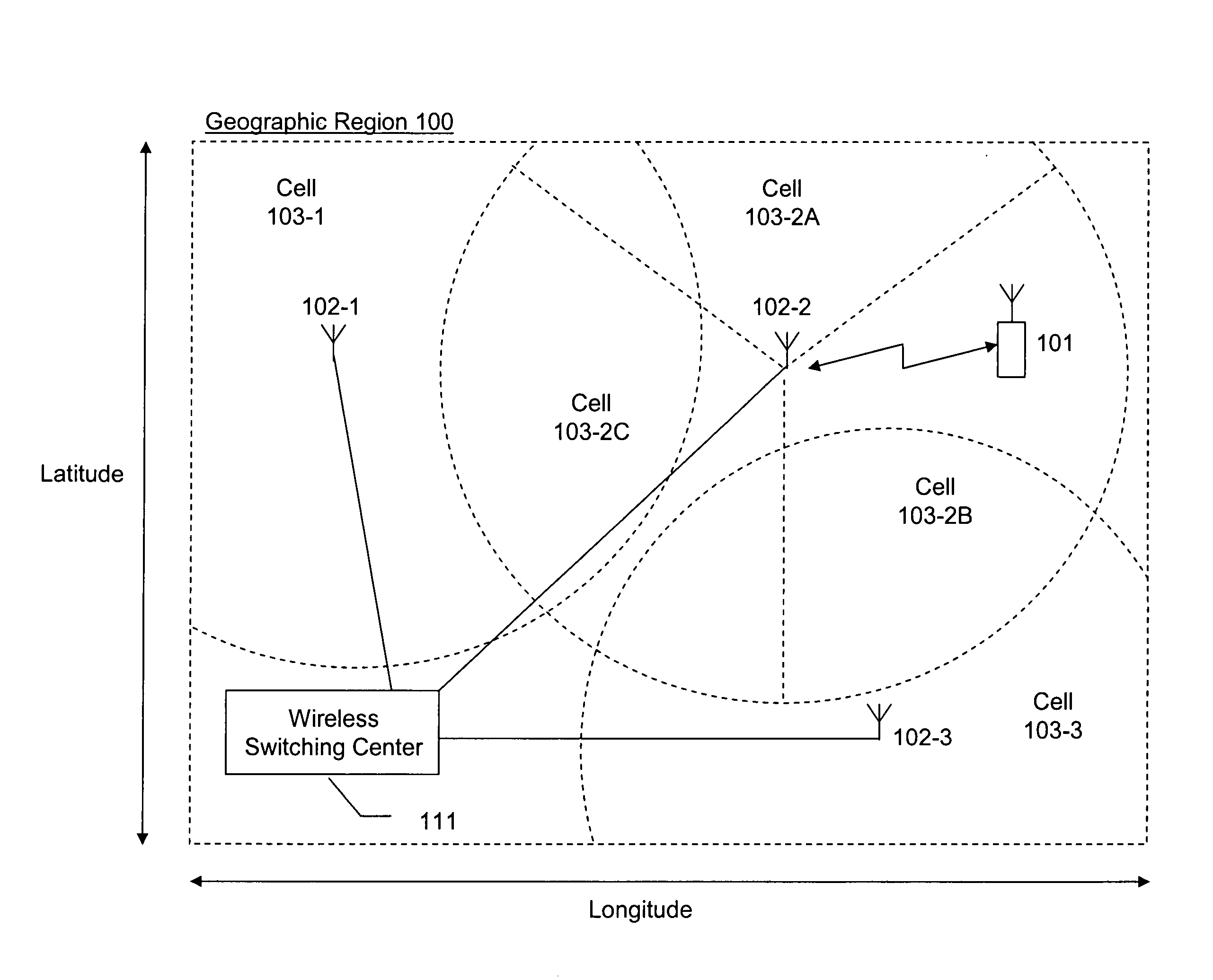
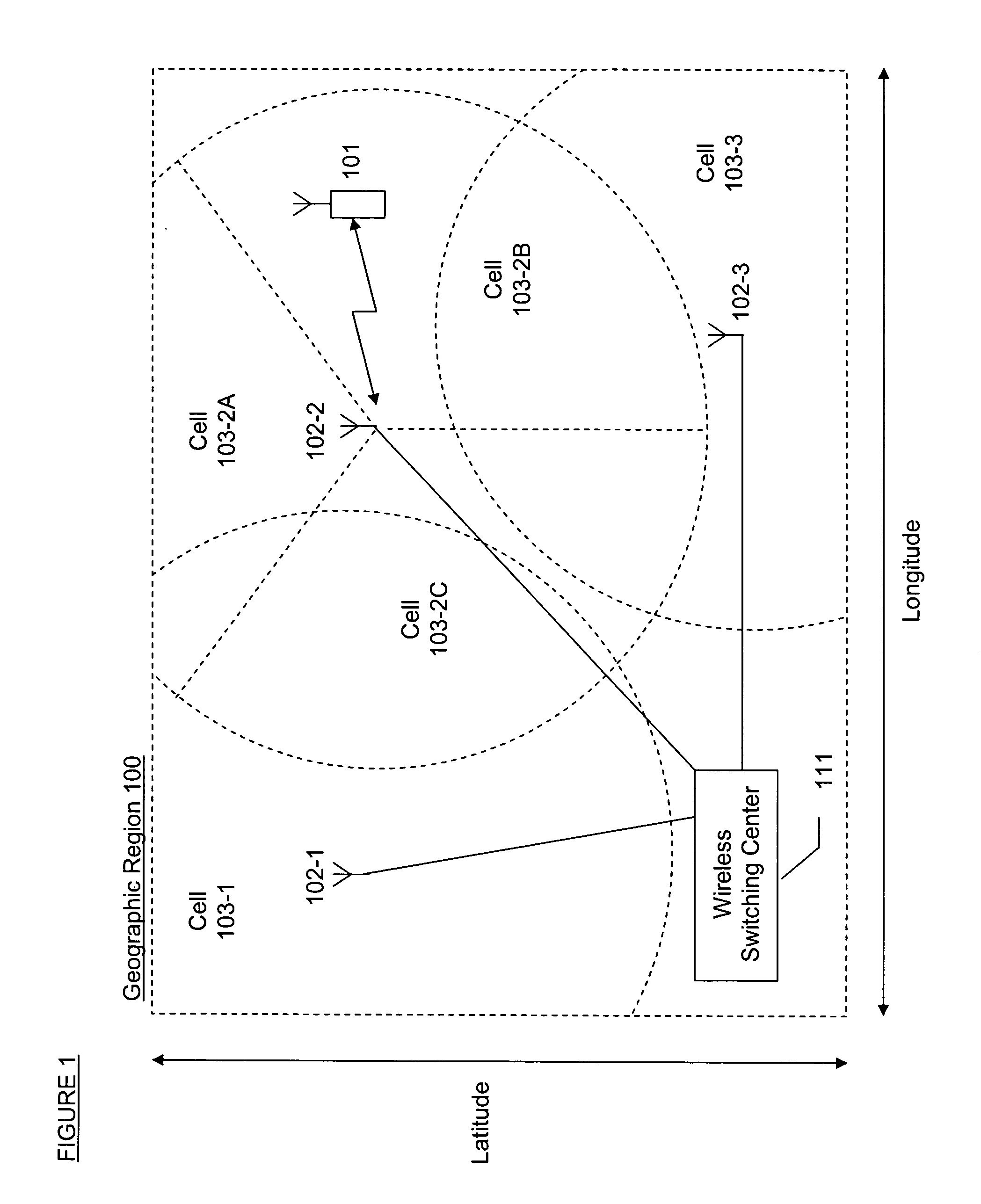
[0044]FIG. 1 depicts the elements of a wireless telecommunications system that provides wireless telecommunications service to wireless terminals (e.g., wireless terminal 101, etc.) within geographic region 100. The hub of the telecommunications system is wireless switching center 111, which might also be known as a mobile switching center (“MSC”) or a mobile telephone switching office (“MTSO”).

[0045]Typically, wireless switching center 111 is connected to a plurality of base stations (e.g., base stations 102-1, 102-2, and 102-3 ), which are dispersed throughout the geographic area serviced by the system. Each base station has one or more cells (e.g., cells 103-1, 103-2A, 103-2B, 103-2C, and 103-3 ) each corresponding to a specific antenna and serving a specific portion of the geographic region 100. As shown in FIG. 1, a cell may be omni-directional (e.g., 103-1 and 103-3 ) or may be limited to a specific angular sector (e.g., 103-2A, 103-2B, and 103-2C). It is well known that opera...


PUM


Abstract

A method and apparatus for estimating the location of a wireless terminal are disclosed. The location of the wireless terminal is estimated based on one or more signal strength measurements in conjunction with: (i) one or more angle-of-arrival measurements, (ii) one or more time-of-arrival measurements, or (iii) a combination of (i) and (ii). At each measurement time, the illustrative embodiment (a) determines the candidate locations for the wireless terminal, (b) computes a measurement likelihood function for any signal strength measurements that are available at that time, (c) computes a measurement likelihood function for any geometry-of-arrival measurements that are available at that time, (d) computes a joint likelihood function for all measurements available at that time, and (e) updates the location probability distribution for the wireless terminal with the joint measurement likelihood function. Estimates of the location of the wireless terminal are obtained from the location probability distribution.

Description

CROSS-REFERENCE TO RELATED APPLICATION[0001]This application claims the benefit of:[0002](i) U.S. provisional application Ser. No. 60 / 461,219, filed Apr. 8, 2003, entitled “Location Estimation of Wireless Terminals Based on Combinations of Signal Strength Measurements, Angle-of-Arrival Measurements, and Time-Difference-of-Arrival Measurements,”[0003](ii) U.S. provisional application Ser. No. 60 / 449,569, filed Feb. 24, 2003, entitled “Location Estimation of Wireless Terminals Based on Combinations of Signal Strength Measurements, Angle-of-Arrival Measurements, and Time-Difference-of-Arrival Measurements,”[0004](iii) U.S. provisional application Ser. No. 60 / 488,855, filed Jul. 19, 2003, entitled “Location Estimation of Wireless Terminals Based on Combinations of Signal Strength Measurements, Angle-of-Arrival Measurements, and Time-Difference-of-Arrival Measurements,”all of which are incorporated by reference.[0005]The underlying concepts, but not necessarily the nomenclature, of the f...

Claims


Application Information

Patent Timeline
IPC IPC(8): H04Q7/20H04W64/00
CPCH04W64/00
Inventor SPAIN, JR., DAVID STEVENSON
Owner POLARIS WIRELESS
Why Eureka
Try Eureka