
Bug killing device

a technology of insect killing device and kill device, which is applied in the direction of insect catchers and killers, electrical equipment, animal husbandry, etc., can solve the problems of increasing the cost of fuel used to create or supply carbon dioxide to the device, requiring users to purchase relatively expensive fuel or gas containers, and causing safety hazards

Inactive Publication Date: 2007-06-26
WELCH TOMMY D
View PDF44 Cites 29 Cited by
  • Summary
  • Abstract
  • Description
  • Claims
  • Application Information

AI Technical Summary

Benefits of technology

"The invention is a bug killing device that uses carbon dioxide to attract and kill insects. The device has a combustion chamber with a candle, an electrified grid, and a bait receptacle. The heated gases from the burning candle warm the bait and evaporate it into the electrified grid to kill the insects. The device can also have a cooling chamber to redirect the carbon dioxide to the electrified grids. The invention can also use a fan to distribute the baited air, a bait chamber that can isolate a secondary bait, and multiple light sources to attract the insects towards the device."

Problems solved by technology

One drawback with known devices is the expense of the fuels used to create or supply carbon dioxide to the device.
Both of these devices have pressurized containers which create a safety risk.
These devices also require the users to purchase relatively expensive fuel or gas containers as they are depleted.

Method used


Image

  • Bug killing device
  • Bug killing device
  • Bug killing device

Examples


first embodiment

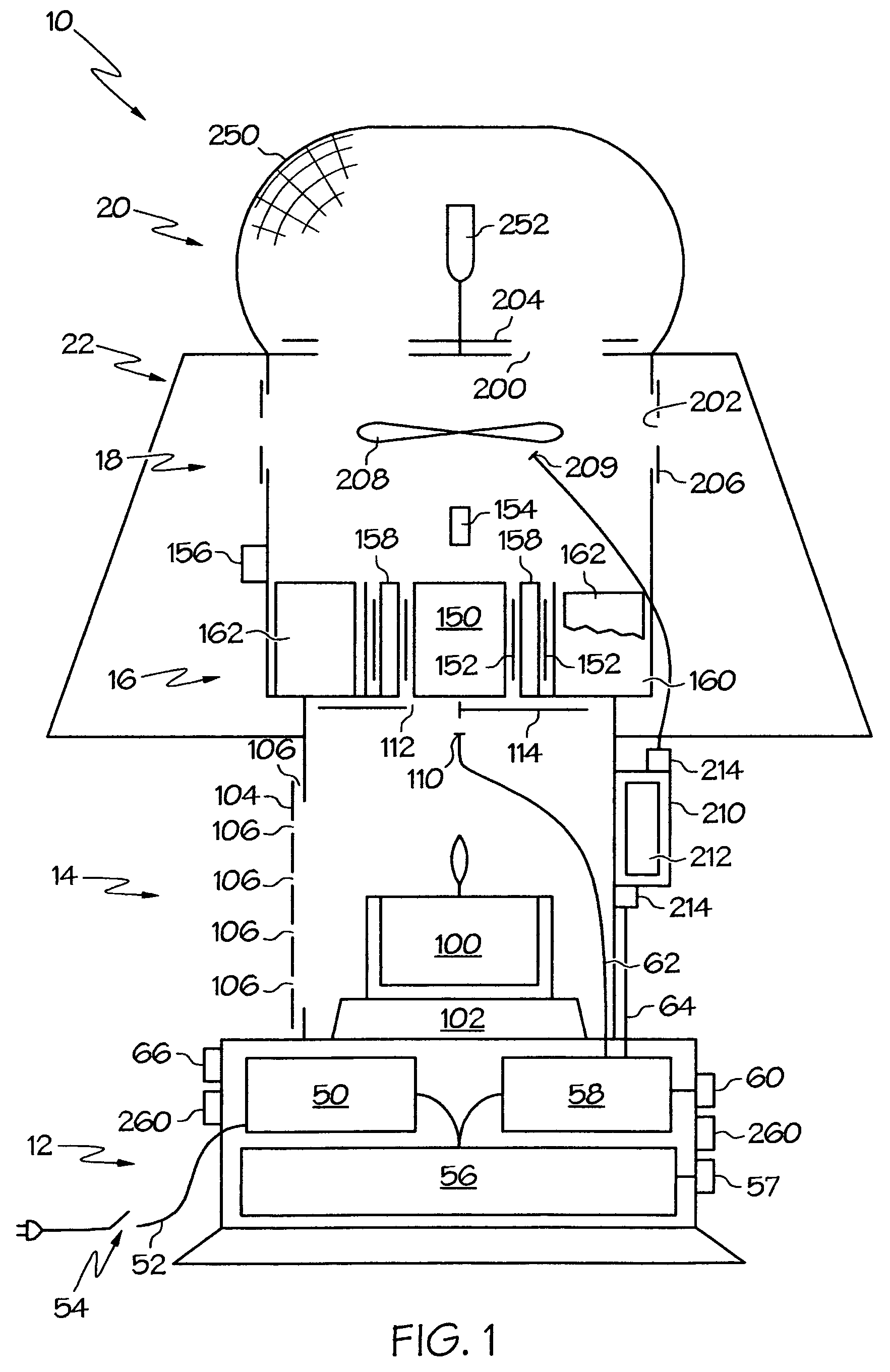
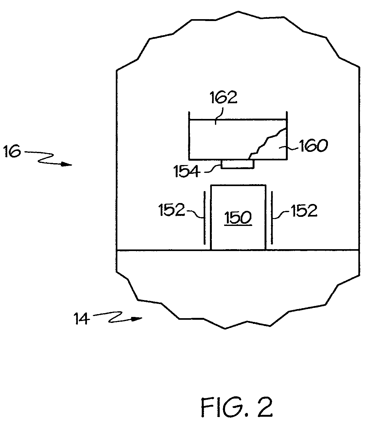
[0022]the insect killing device of the present invention is indicated generally by the numeral 10 in the accompanying drawings. In one embodiment, device 10 generally includes a control box 12, a combustion chamber 14, a catalyst chamber 16, a mixing chamber 18, a grid assembly 20, and an umbrella 22. Device 10 functions to lure bugs to device 10 and to kill bugs once they arrive. When used outside, device 10 uses carbon dioxide as the primary bait for the bugs. In addition, device 10 may use a scented bait to help lure the bugs. Device 10 may also use light sources to lure the bugs. Device 10 also uses heat to lure the bugs. When used inside to attract flies, device 10 relies on the scented bait, heat, and lights to attract the insects. Device 10 kills the bugs using at least one of an electrified grid and a sticky umbrella 22 that may be used alone or in combination.

[0023]Control box 12 generally includes a power supply 50, a power line 52, and a switch 54. Switch 54 allows the us...

second embodiment

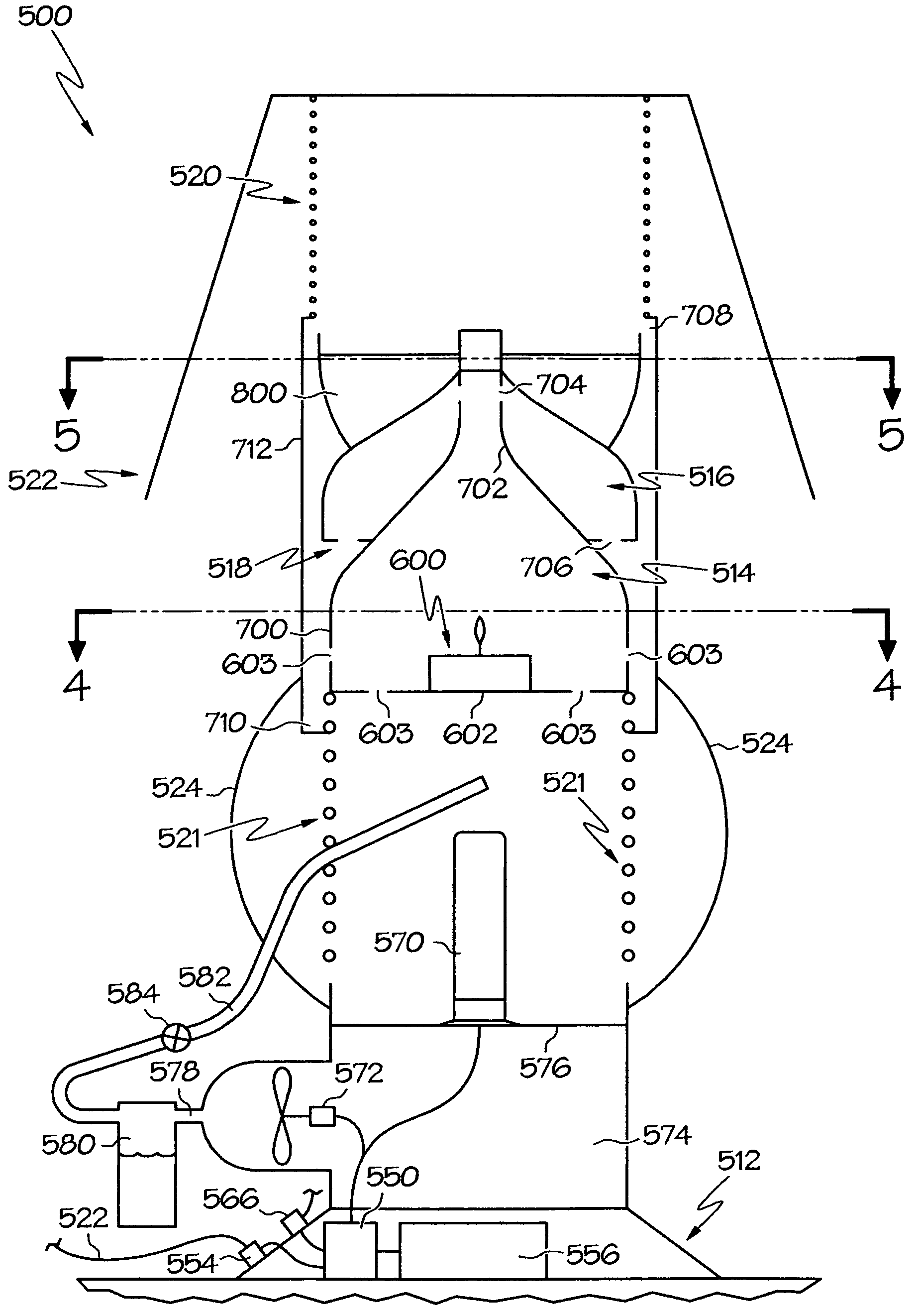
[0041]the insect killing device of the present invention is indicated generally by the numeral 500 in the accompanying drawings. In one embodiment, device 500 generally includes a control box 512, a combustion chamber 514, a cooling chamber 516, a mixing chamber 518, first and second grid assemblies 520,521 and an umbrella 522. Umbrella 522 protects first grid 520 while a cage 524 protects second grid 521. Cage 524 may also be sticky to catch bugs. Umbrella 522 may also protect device 500 from rain. Device 500 functions to lure bugs to device 500 and to kill bugs once they arrive. When used outside, device 500 uses carbon dioxide as the primary bait for the bugs. In addition, device 500 may use a scented bait to help lure the bugs. Device 500 may also use light sources to lure the bugs. Device 500 also uses heat to lure the bugs. When used inside to attract flies, device 500 relies on the scented bait, heat, and lights to attract the insects. Device 500 kills the bugs using at least...


PUM


Abstract

A bug killing device includes a body that defines a combustion chamber with a candle disposed in the combustion chamber. The burning candle produces heated gases that include carbon dioxide. A first bait receptacle is disposed above the combustion chamber with bait being disposed in the first bait receptacle such that the heat from the burning candle warms the bait receptacle to evaporate bait into an electrified grid.

Description

CROSS REFERENCE TO RELATED APPLICATIONS[0001]This application claims priority from U.S. Provisional Patent Application Ser. No. 60 / 529,816 filed Dec. 16, 2003; the disclosures of which are incorporated herein by reference.BACKGROUND OF THE INVENTION[0002]1. Technical Field[0003]The present invention generally relates to insect killing devices and, more particularly, to the class of insect killing devices that uses a bait to lure the insects toward the device. Specifically, the present invention combines the use of lures to draw insects, particularly mosquitos, towards an electrified grid and / or sticky umbrella.[0004]2. Background Information[0005]Home and business owners desire to reduce or eliminate the number of biting insects, particularly mosquitos, from their backyards and business areas. Numerous traps, sprays, and killing devices are known in the art for reducing the number of biting insects from these areas. These devices include those that use various types of baits and lur...

Claims


Application Information

Patent Timeline
Patent Type & Authority Patents(United States)
IPC IPC(8): A01M1/20A01M1/02A01M1/04A01M1/14A01M1/22
CPCA01M1/02A01M1/023A01M1/04A01M1/14A01M1/145A01M1/223A01M2200/012
Inventor WELCH, TOMMY D.
Owner WELCH TOMMY D
Learn More