Modular aerospace plane

a technology of aerospace planes and modules, applied in the field of modules, can solve the problems of reducing supersonic performance, major shifts in aerodynamic balance, safety and technology challenges, etc., and achieves the effects of reducing manufacturing costs, improving safety, performance and versatility, and minimal sonic boom disturban

Inactive Publication Date: 2007-06-26
TALMAGE JR ROBERT N
View PDF95 Cites 54 Cited by
  • Summary
  • Abstract
  • Description
  • Claims
  • Application Information

AI Technical Summary

Benefits of technology

[0009]It is an object of the present invention to provide a new aerospace vehicle with improved safety, performance, and versatility over existing vehicles, with the ability to change wings, select different aircraft modules which integrate into the aircraft platform to support vario

Problems solved by technology

Previous work on variable sweep wings aircraft such as the F-14 Tomcat, The F-111 Aardvaark, and the B-1B Bomber have been able to improve take off and landing performance over other supersonic vehicles yet they suffer major shifts in aerodynamic balance and reduced supersonic performance with the additional weight and complexity of the variable sweep wings.
Previous work on the oblique wing has not produced a production aircraft and furthermore, still faces safety and technological challenges.
However, the Concorde has recently bee

Method used


Image

  • Modular aerospace plane
  • Modular aerospace plane
  • Modular aerospace plane

Examples


Embodiment Construction

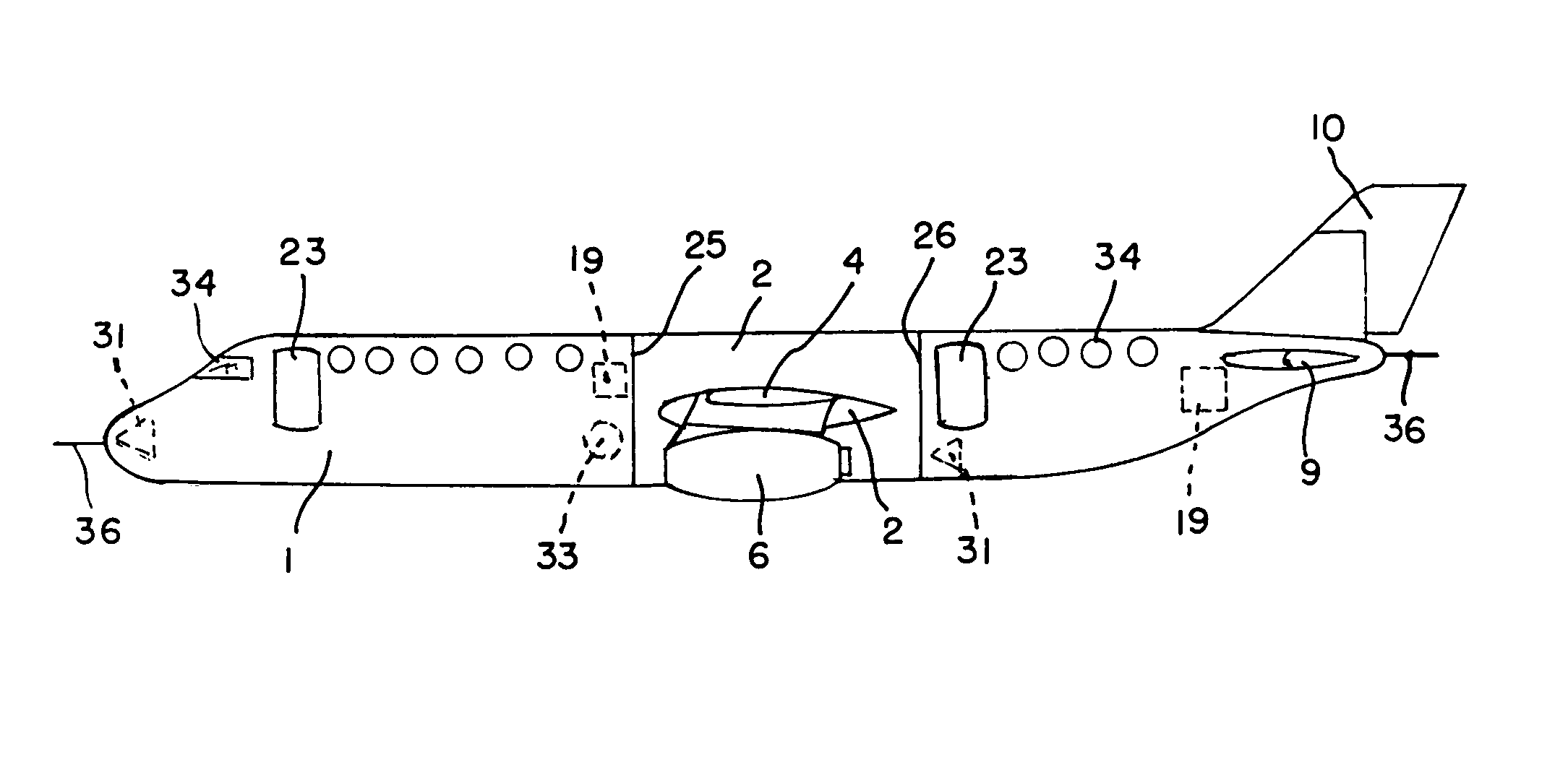
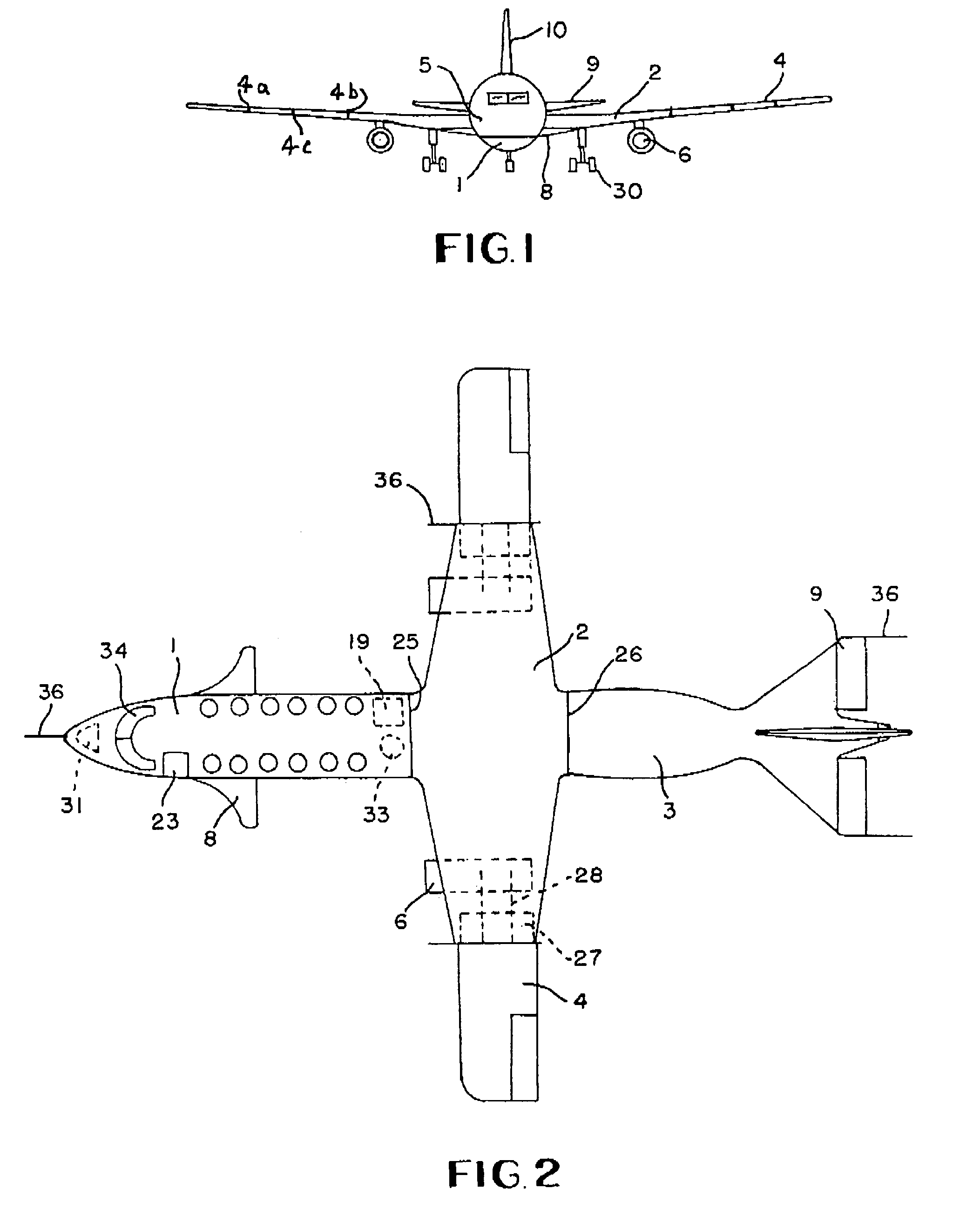
[0036]With reference to FIG. 1 of the drawings, the illustrated vehicle demonstrates the relative position of the four lifting surfaces, the canard 8, the main wing 2, the wing attachments 4 and the elevators 9. Numerals 4a, 4b and 4c in FIG. 1 designate the wing tips of wing attachment 4 which are of varying lengths. The location of these flight surfaces will have a beneficial effect on each other to improve lift, aerodynamic performance and balance. In level cruise attitude, the frontal cross section area of the canard and the elevator disappear into the main wing to minimize drag and sonic disturbance.

[0037]The configuration of the Stable Center of Lift (SCL) main wing design will restrict movement of the center of lift, permit the utilization of the wing attachments 4 and reduce cost. For purposes of flight control, ailerons 4a are mounted on wing attachments 4. In order to offer improved aerodynamic balance and efficient aerodynamic control, the main wing section 2 is also conf...


PUM


Abstract

This invention relates to the design of a Modular Aerospace Plane (MAP) comprising a forward fuselage section, a main wing section, a tail section and wing attachments. Various sections can be integrated to offer a variety of aircraft characteristics, performance and missions. This modular design offers a new method of aircraft fabrication, maintenance, repair and ground handling to reduce costs for the manufacturers, owners and operators. The forward fuselage and tail sections may utilize a parachute device whereby these sections can separate in an emergency and safely lower the occupants to the ground.

Description

[0001]The benefits under 35 U.S.C. 119 are claimed of provisional patent application 60 / 528,307 filed Dec. 11, 2003.FIELD OF THE INVENTION[0002]The present invention, generally, relates to a new and improved system involving a method and an apparatus, by which a Modular Aerospace Plane (MAP), comprising modular components, a forward fuselage section, a main wing section, wing attachments, and a tail section can operate as an aerospace vehicle with improved levels of performance in speed, altitude, range, aerodynamic balance, STOL, versatility, economics and whereby occupants can survive any in-flight emergency over land or water in an escape module. When equipped with rocket propulsion, the MAP can fly into space and re-enter the atmosphere for a conventional landing.BACKGROUND OF THE INVENTION[0003]It has been a long felt need to design an aircraft with the ability to fly various missions, whereby, the plane can quickly change between a Short Take Off and Landing (STOL) aircraft, a...

Claims


Application Information

Patent Timeline
IPC IPC(8): B64C1/00
CPCB64C1/00B64C39/024B64D25/12B64C2211/00
Inventor TALMAGE, JR., ROBERT N.
Owner TALMAGE JR ROBERT N
Why Eureka
Try Eureka