
Three-dimensional image display device creating three-dimensional image directly from projection data

a display device and image technology, applied in the direction of instruments, nuclear engineering, material analysis using wave/particle radiation, etc., can solve the problems of not being able to examine other objectives of image reconstruction processing, not being able to perform image reconstruction by using desirable image reconstruction parameters, and being unable to perform three-dimensional image processing with this function

Active Publication Date: 2007-06-26
TERARECON
View PDF10 Cites 79 Cited by
  • Summary
  • Abstract
  • Description
  • Claims
  • Application Information

AI Technical Summary

Problems solved by technology

Although each of these usage methods requires parameters optimized for image reconstruction processing, currently, the data that is stored for a long period of time is image data available after image reconstruction, and since long-term storage of projection data prior to the image reconstruction has not been performed because a major computer resource is required for image reconstruction of projection data, there has been no other research of reconstruction processing using optimized image reconstruction processing parameters with each of the respective usage methods.
However, because image data is generally preserved for a long period of time only after image reconstruction, and because long-term storage of the projection data has not been provided, it was thus not possible to examine other objectives of image reconstruction processing which are used for each individual operation.
Also, even when long-term storage has been provided, for example of the projection data of X-ray CT devices, since continuous scanning operations with the X-ray CT devices are conducted as a routine with a plurality of scans, it is impossible for an external user to perform image reconstruction by using desirable image reconstruction parameters, which an external user will need for this projection data.
However, even in a system which is equipped with this function, since continuous scanning operations are conducted routinely with many scans, it is still in fact impossible for an external user to perform three-dimensional image processing with this function.
In other words, the rendering processing did not utilize the projection data set, because reconstruction was very time consuming, so it was not practical to use the projection data for rendering.
However, image reconstruction processing is generally not conducted for this specific purpose because a major storage capacity is needed in order to accumulate projection data.
Further, when long-term storage of projection data is not performed, since most of the time is spent on routine processing performed by image reconstruction devices of X-ray CT devices, the development is not open to users outside of the system.
Therefore, the image reconstruction devices thus cannot be used even if reconstruction of projection data is desirable for three-dimensional images because a major computer resource is needed for reconstruction of images using projection data.

Method used


Image

  • Three-dimensional image display device creating three-dimensional image directly from projection data
  • Three-dimensional image display device creating three-dimensional image directly from projection data
  • Three-dimensional image display device creating three-dimensional image directly from projection data

Examples


Embodiment Construction

[0042]A method and apparatus for creating three-dimensional images directly from projection data are described. References in this specification to “an embodiment”, “one embodiment”, or the like, mean that the particular feature, structure or characteristic being described is included in at least one embodiment of the present invention. Occurrences of such phrases in this specification do not necessarily all refer to the same embodiment.

[0043]In order to solve the problem mentioned above, the present invention includes a three-dimensional image display device which makes it possible to create and display three-dimensional images directly from projection data. In certain embodiments of the invention, the image display device is equipped with a mechanism for accumulation of projection data collected during X-ray scanning, connected to an X-ray CT device, and with a mechanism for displaying of created three-dimensional images using this projection data, without using slice or volume im...


PUM


Abstract

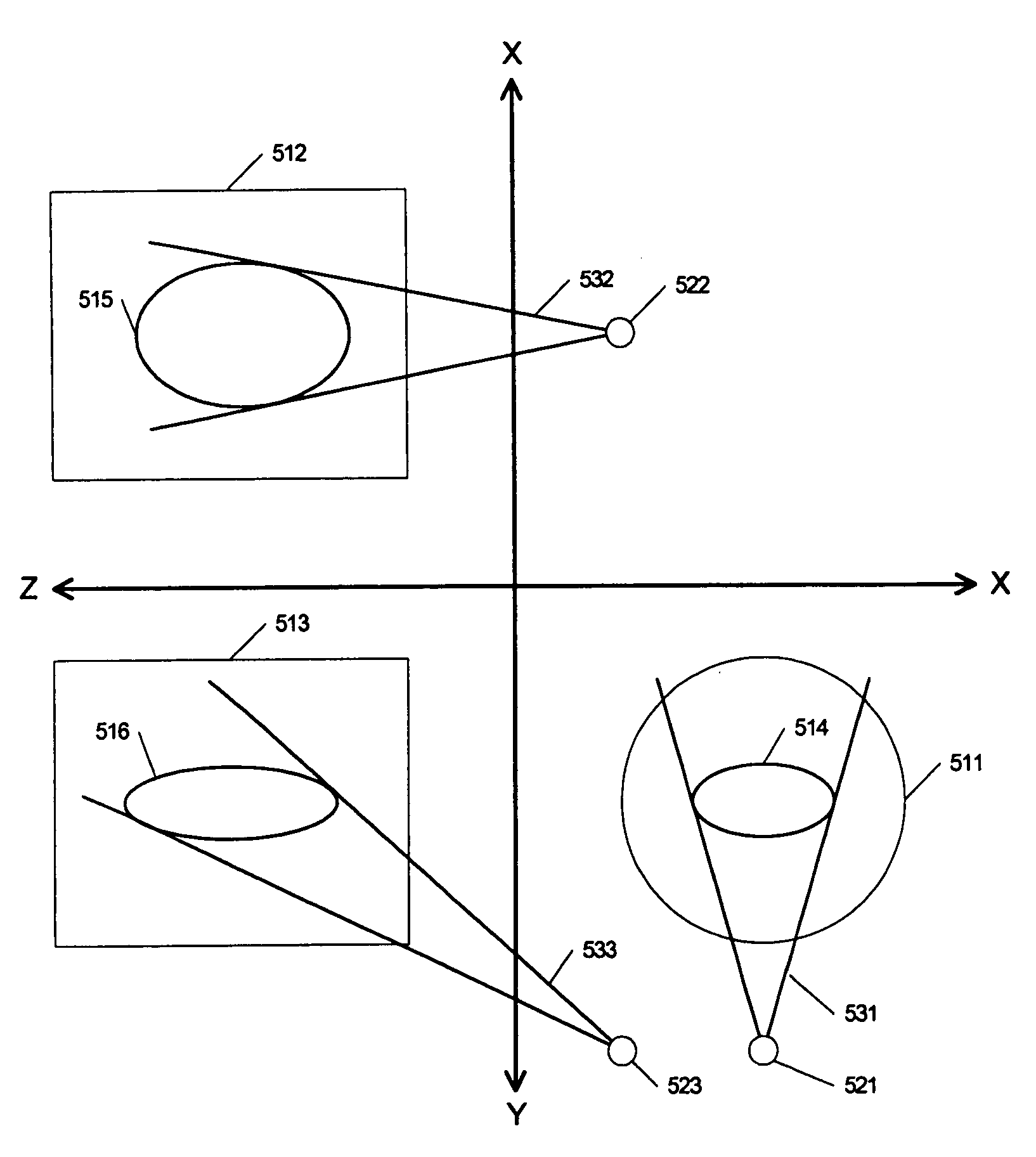
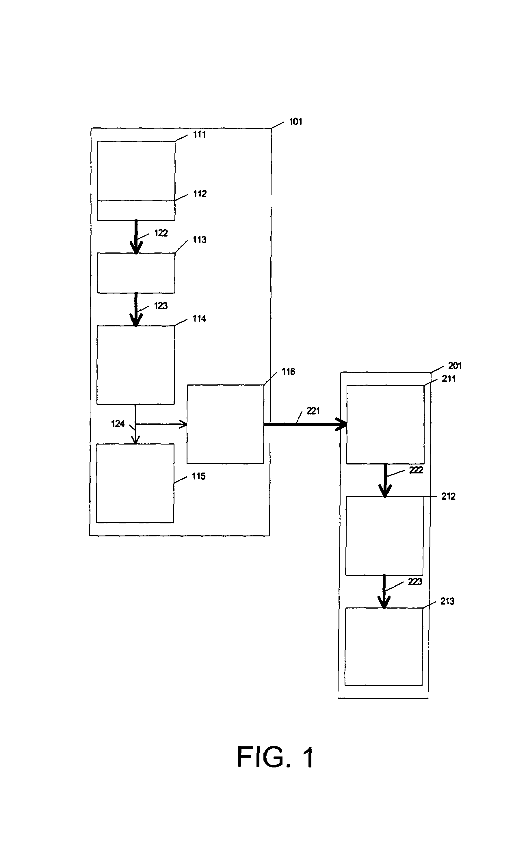
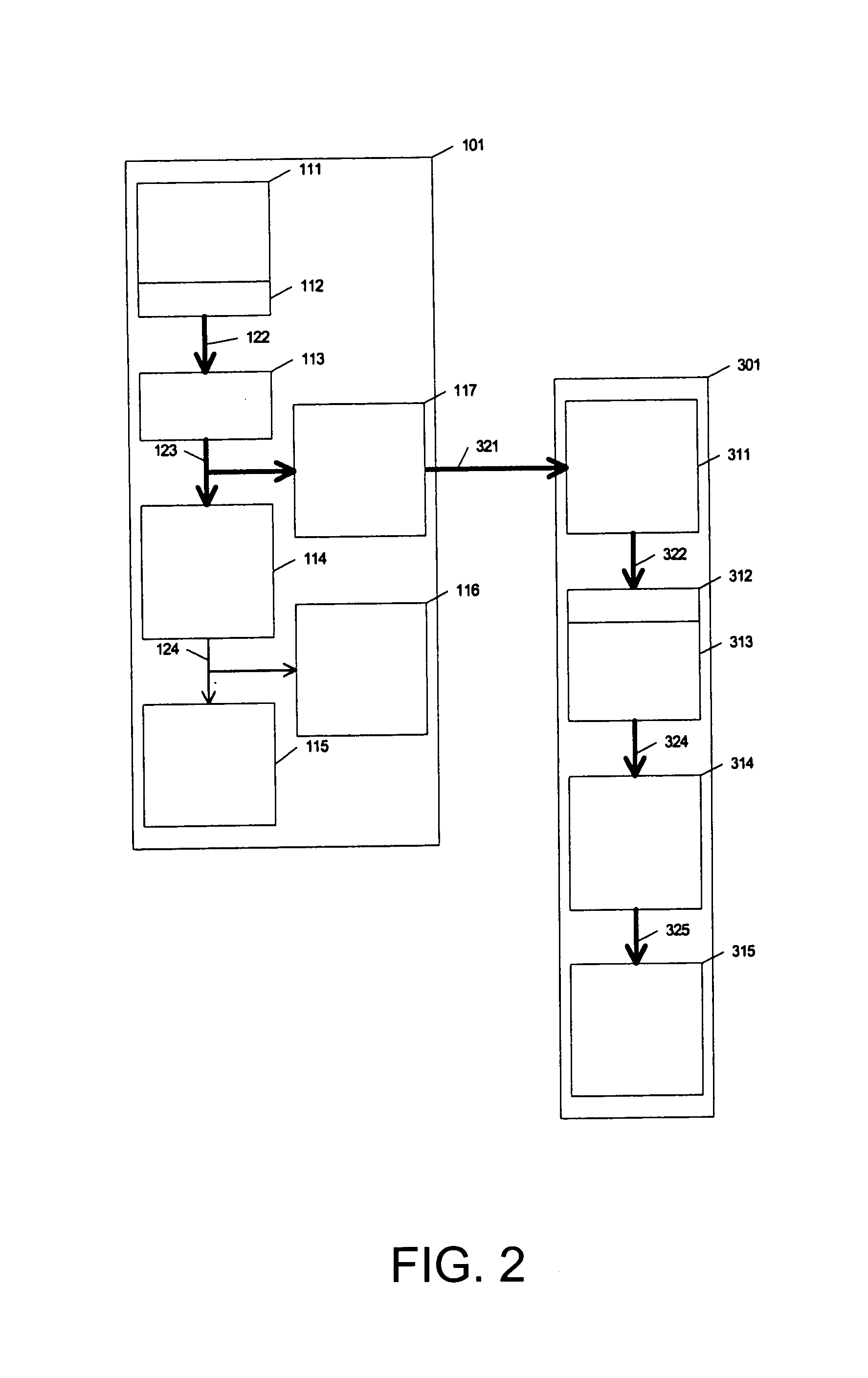
An imaging device accesses projection data collected by a medical imaging system during a scan of a body. The imaging device uses the projection data directly to render an image of a region of interest of the body.

Description

FIELD OF THE INVENTION[0001]This invention relates to a three-dimensional image display device which creates three-dimensional images directly from the projection data of an X-ray computerized tomography (CT) device.BACKGROUND[0002]X-ray CT apparatuses are used to irradiate with X-rays a subject when the periphery of a subject who is lying on the side is irradiated on the table top of a bed. Because the intensity of the X-rays transmitted through the subject is detected with an X-ray detector, projection data can be collected on the horizontal profile of the subject. After the table top of the bed has then been moved, the next projection data can be collected in the same manner for the next horizontal profile (transverse cross-section), so that the projection data can be collected repeatedly by moving the table top until multiple transverse cross-sections of projection data of the subject have been collected by repeating the table top moving and projection data collecting operations...

Claims


Application Information

Patent Timeline
Patent Type & Authority Patents(United States)
IPC IPC(8): H05G1/60
CPCG06T11/008G06T15/06G06T15/08Y10S378/901
Inventor SAITO, MOTOAKITAKAHASHI, KAZUO
Owner TERARECON
Learn More