Supercharge Your Innovation With Domain-Expert AI Agents!

Method of calculating internal signals for use in a map algorithm

a map algorithm and internal signal technology, applied in the field of calculating internal signals used in map algorithms, can solve the problems of burdened turbo decoders with the task of performing with very high processing speed, and achieve the effect of improving pipelining

Active Publication Date: 2007-06-26
WIPRO LTD
View PDF5 Cites 0 Cited by
  • Summary
  • Abstract
  • Description
  • Claims
  • Application Information

AI Technical Summary

Benefits of technology

[0057]The described embodiment of the invention is a modification of the calculations of decoding signals α and / or β in algorithm to allow for an improved pipelining implementation and allows S2(t+1) to be independent of the normalization in t, and can begin computation as soon as S2(t) is completed. The described embodiment also retains the same final values of the internal signals (the values after S4) as the prior art.

Problems solved by technology

However, as time progresses and demand for high data rate communication increases, the turbo decoder is burdened with the task of performing with very high processing speed.

Method used


Image

  • Method of calculating internal signals for use in a map algorithm
  • Method of calculating internal signals for use in a map algorithm
  • Method of calculating internal signals for use in a map algorithm

Examples


first embodiment

[0062]The embodiments of the invention use modified max-log-MAP algorithms and a first embodiment will now be described.

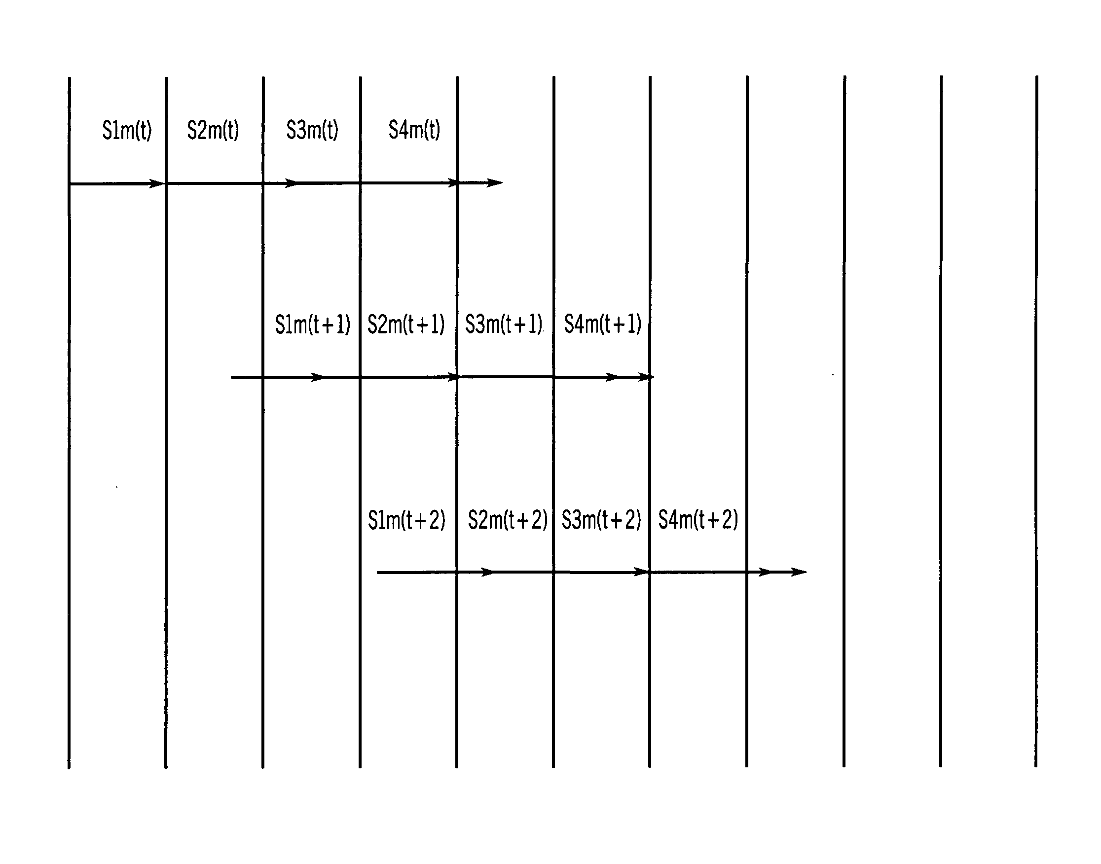
[0063]In the modified algorithm, the computations for α / β are modified so that pipelining implementation can be faster than that of the prior art. The main feature is to make the computation of α / β of symbol sequence t+1 independent of the normalization of α / β of symbol sequence t.

[0064]Equation (1) is modified so that αt(m) is computed using unnormalized values αt−1(m) instead of normalized values αt−1(m), and a normalized constant At−1 is added.

αt(m)=max-of-2{αt−1(m0)+Υ0t−1(m0), αt−1(m1)+Υ1t−1(m1)}−At−1  (8)

[0065]Equation (2) remains the same.

αt(m)=αt(m)−At  (9)

[0066]Similarly, equations (4) and (5) are modified to

βt(m)=max-of-2{βt+1(m0)+Υ0t(m), βt+1(m1)+Υ1t(m)}−Bt−1  (10)

βt(m)=βt(m)−Bt  (11)

[0067]The final values of αt and βt are still exactly the same as the prior art.

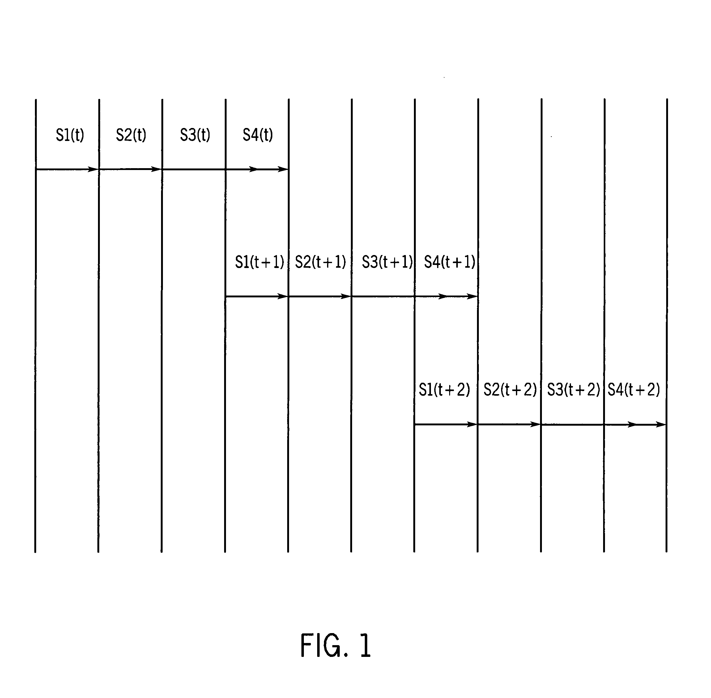
[0068]Following these modifications, the four dependent sequential stages described in the pri...

second embodiment

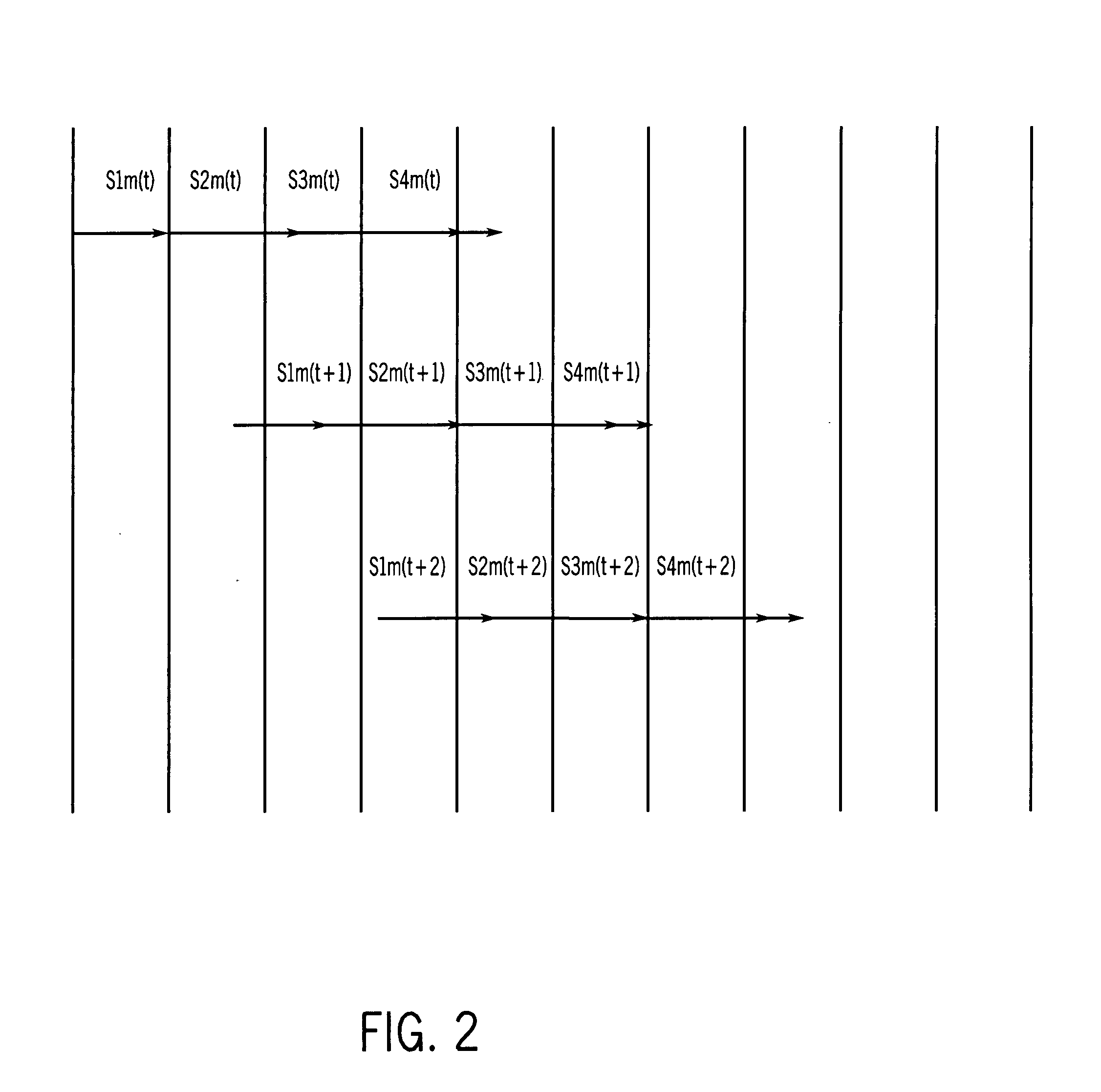
[0088]The stages S1m and S3m are still the same, but S2m and S4m are slightly different. For example, for α computation of second embodiment, the four stages are[0089]S1m2(t): Compute Υ0t−1(m0) and Υ1t−1(m1) using Table 1[0090]S2m2(t): Compute αt(m) using equation (16)[0091]S3m2(t): Compute At using one of the equations (3a), (3b), (3c)[0092]S4m2(t): Compute αt(m) using equation (17), and store (A1+A2+ . . . +At) for future use (in the next symbol sequence t+1)

[0093]Compared with the prior art, the length of time taken for these modified stages is almost the same. S1 and S1m2 take exactly the same computation time, and so do the pair S2 and S2m and the pair S3 and S3m. S4m2 is only two times longer than S4 because instead of subtracting one constant, S4m2 subtracts two constants (the second one is the stored value from the previous S4m2 symbol).

[0094]In general, the length of time taken to complete the stages given L number of symbols is

Tm=T1m+T2m+T3m+L×T4m  (20)

[0095]By comparing w...


PUM


Abstract

A method of calculating internal signals for use in a MAP algorithm is disclosed, comprising the steps of:obtaining first decoding signals by processing received systematic and received encoded symbols of each symbol sequence of a received signal;obtaining unnormalized second decoding signals for the current symbol sequence by processing the first decoding signals of the previous sequence and second decoding signals of the previous sequence;obtaining unnormalized third decoding signals for the current symbol sequence by processing the first decoding signals of the current sequence and third decoding signals of the next sequence;normalizing the unnormalized second and third decoding signals; andwherein at least one of said second decoding signals of the previous sequence and said third decoding signals of the next sequence are unnormalised.

Description

FIELD OF THE INVENTION[0001]This invention relates to the method for calculating internal signals used in a MAP algorithm, more particularly, but not exclusively, for use in the max-log-MAP (maximum a posteriori) algorithm.BACKGROUND OF THE INVENTION[0002]The max-log-MAP decoding algorithm is a simplified version of the MAP decoding algorithm, which is also known as the BCJR decoding algorithm. The max-log-MAP is used to decode a convolutional encoder. It is one of the more popular soft output decoding methods.[0003]A main application of the max-log-MAP decoder is in the decoding of turbo codes, which are generated using two parallel concatenated convolutional encoders. Two max-log-MAP decoders are used as component decoders in the turbo decoder. Today, turbo codes have become established as an important method of channel coding in the third generation wireless mobile communication technical specification. However, as time progresses and demand for high data rate communication incre...

Claims


Application Information

Patent Timeline
Patent Type & Authority Patents(United States)
IPC IPC(8): G11C29/00G06F7/00G06F17/00H03M13/37H03M13/45
CPCH03M13/3905H03M13/6583
Inventor PAN, JU YANKATSURAGAWA, HIROSHI
Owner WIPRO LTD
Features
  • R&D
  • Intellectual Property
  • Life Sciences
  • Materials
  • Tech Scout
  • Unparalleled Data Quality
  • Higher Quality Content
  • 60% Fewer Hallucinations
Learn More