Assembly comprising a gas turbine combustion chamber integrated with a high pressure turbine nozzle

Active Publication Date: 2007-07-03
SN DETUDE & DE CONSTR DE MOTEURS DAVIATION S N E C M A
View PDF16 Cites 55 Cited by
  • Summary
  • Abstract
  • Description
  • Claims
  • Application Information

AI Technical Summary

Benefits of technology

[0011]locking members preventing the turbine nozzle from turning about its axis relative to at least one of the metal shrouds, so as to avoid the forces exerted on the turbine nozzle vanes by the gas flow coming from the combustion chamber being taken up by the portions of the connection ferrules that extend between the combustion chamber and turbine nozzle assembly and the metal shrouds.

Problems solved by technology

Although integrating the HP turbine nozzle with the combustion chamber presents the above-mentioned advantages, it nevertheless also presents the following problem.

Method used


Image

  • Assembly comprising a gas turbine combustion chamber integrated with a high pressure turbine nozzle
  • Assembly comprising a gas turbine combustion chamber integrated with a high pressure turbine nozzle
  • Assembly comprising a gas turbine combustion chamber integrated with a high pressure turbine nozzle

Examples


Embodiment Construction

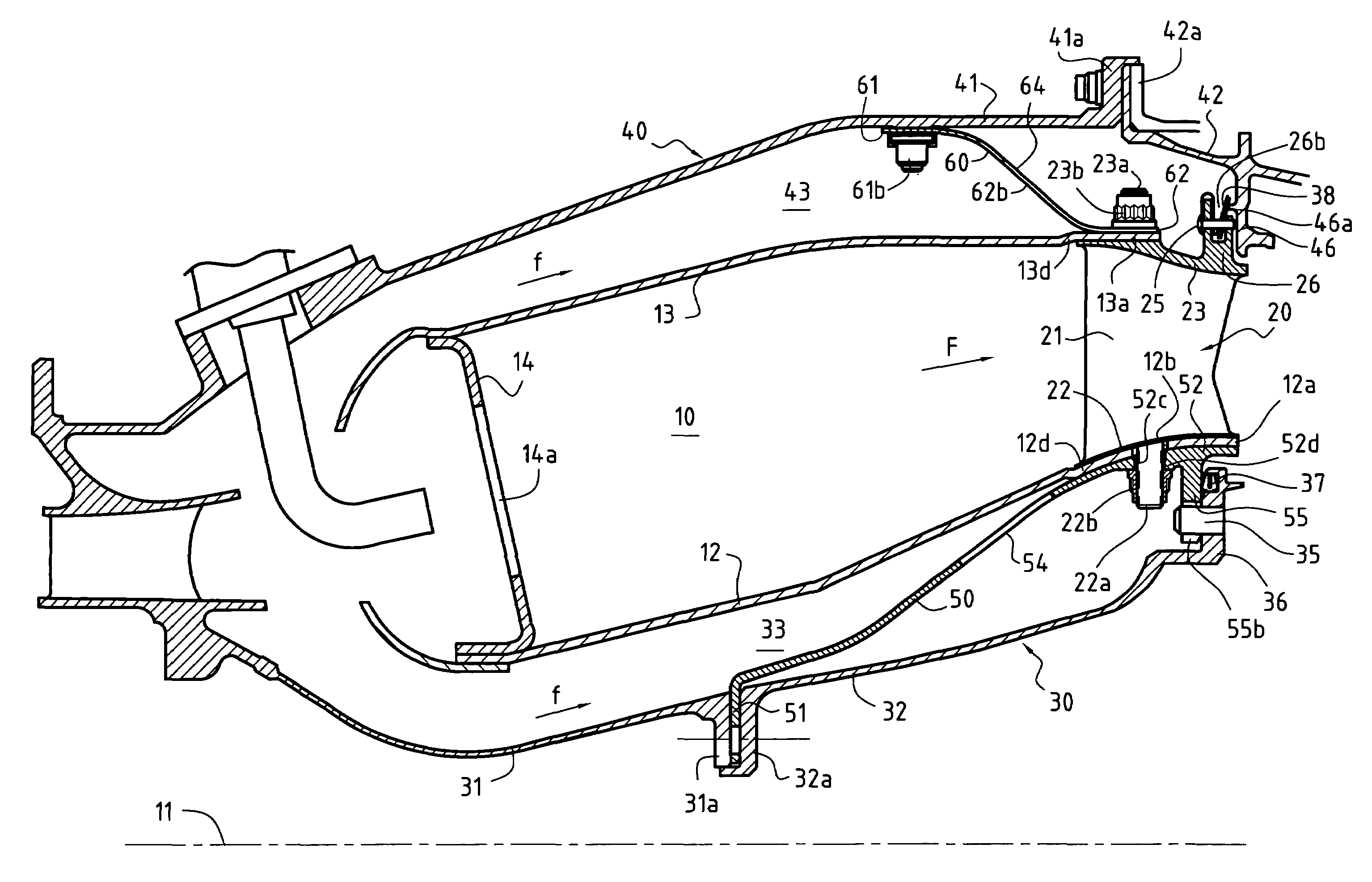
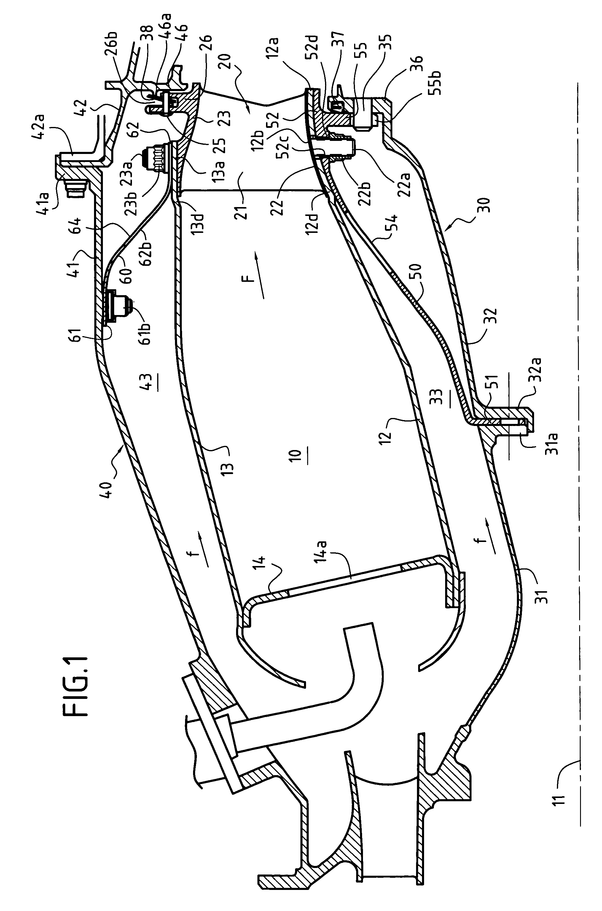
[0022]FIG. 1 is an axial half-section of a gas turbine comprising an annular combustion chamber 10, a high pressure turbine nozzle 20 mechanically connected to a downstream end portion of the chamber 10, inner and outer annular metal shrouds 13 and 14, and connection ferrules 50 and 60 holding the assembly constituted by the chamber 10 and the nozzle 20 in the space defined between the shrouds 30 and 40.

[0023]The combustion chamber 10 is defined by an inner annular wall 12 and an outer annular wall 13 having a common axis 11, and by an upstream end wall 14 secured to the annular walls 12 and 13. In well-known manner, the end wall 14 presents a series of orifices 14a distributed around the axis 11 to receive injectors enabling fuel and oxidizer to be injected into the combustion chamber.

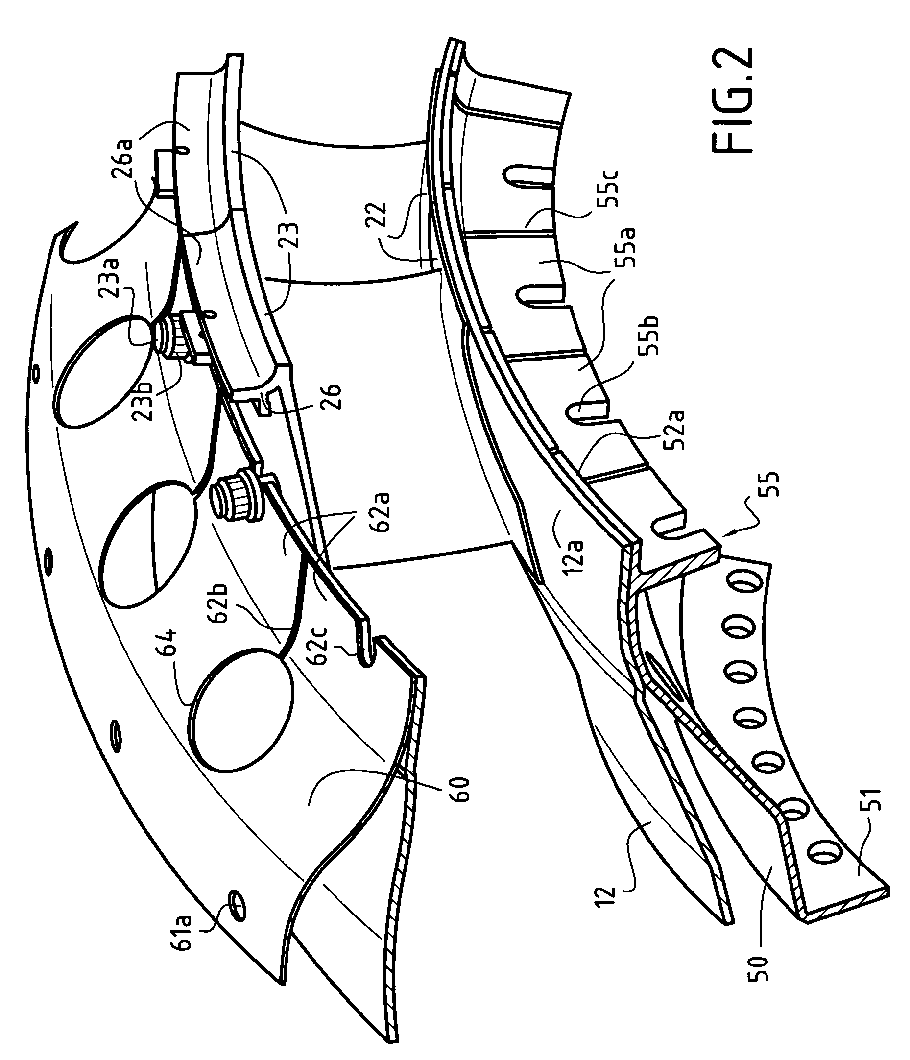
[0024]The HP turbine nozzle 20, which constitutes the inlet stage of the turbine, comprises a plurality of stationary vanes angularly distributed around the axis 11. As shown in FIGS. 2 and 3, the van...


PUM


Abstract

The high pressure turbine nozzle is mechanically connected to a downstream end portion of the combustion chamber and inner and outer connection ferrules connect the combustion chamber and turbine nozzle assembly to inner and outer metal shrouds in order to hold said assembly between the shrouds. Locking members are provided to prevent the turbine nozzle from turning about its axis relative to at least one of the metal shrouds so as to prevent the forces that are exerted on the turbine nozzle vanes by the flow of gas coming from the chamber being taken up by the portions of the connection ferrules that extend between the combustion chamber and turbine nozzle assembly and the metal shrouds.

Description

BACKGROUND OF THE INVENTION[0001]The invention relates to gas turbines, in particular for airplane engines or industrial turbines. More particularly, it relates to an assembly comprising a combustion chamber integrated with a high pressure turbine nozzle.[0002]In a gas turbine comprising an annular combustion chamber, proposals have already been made to mount the high pressure (HP) turbine nozzle constituting the inlet stage of the turbine by connecting it mechanically to the downstream end portion of the combustion chamber (throughout this application the terms “upstream” and “downstream” are used relative to the flow direction of the gas stream through the combustion chamber and the nozzle). The assembly constituted by the combustion chamber and the HP turbine nozzle can then be supported by connection ferrules, themselves connected to inner and outer metal shrouds.[0003]Such a disposition makes it possible to ensure better continuity for the gas flow stream at the interface betwe...

Claims


Application Information

Patent Timeline
Patent Type & Authority Patents(United States)
IPC IPC(8): F23R3/42F01D9/02F01D9/04F01D25/24
CPCF01D9/023F01D9/041F01D25/246F23R3/007F23R3/60F05B2230/606Y02T50/672Y02T50/675F05D2230/642Y02T50/60
Inventor AUMONT, CAROLINECONETE, ERICDE SOUSA, MARIOHERNANDEZ, DIDIER
Owner SN DETUDE & DE CONSTR DE MOTEURS DAVIATION S N E C M A
Why Eureka
Try Eureka