DC superconducting cable

a superconducting cable and direct current technology, applied in the direction of superconductors/hyperconductors, superconducting magnets/coils, magnetic bodies, etc., can solve the problems of reducing the cooling effect of the cooling devi

Inactive Publication Date: 2007-07-03
SUMITOMO ELECTRIC IND LTD
View PDF13 Cites 16 Cited by
  • Summary
  • Abstract
  • Description
  • Claims
  • Application Information

AI Technical Summary

Benefits of technology

[0025]By using the above-described DC superconducting cable, both bipolar transmission and monopole transmission can be implemented. In this case, the use of the three cores can be selected as desired. When performing bipolar transmission, the respective cores can be used as a positive electrode core, a negative electrode core, and a neutral line core, the neutral line core being used as a spare for the positive electrode core and the negative electrode core. When performing monopole transmission, a superconducting cable provided with a return-current conductor for each core can be used as a channel for a return current. Regardless of whether bipolar transmission or monopole transmission is performed, three cores can be cooled at the same time, thereby making it possible to simplify the cooling mechanism. Further, since three cores are stranded, a means for compensating thermal contraction occurring during cooling can be easily provided.

Problems solved by technology

However, AC loss is caused by the inductance, and the transmission current is restricted to that extent.
Also, in the AC line system, the short-circuit current becomes large in the event of failure, and as a result, the temperature increases, which is also disadvantageous.
(1) It is difficult to simplify the cooling system.
However, since the superconducting cables are independently cooled in practice, the system becomes complicated, and the system cost also increases.
(2) It is difficult to take measures against the contraction of cable cores occurring during cooling.
However, in DC superconducting cables using single-core cables, measures against contraction cannot be taken by the adjustment of stranding.
Thus, it is difficult to implement measures against the contraction.

Method used


Image

  • DC superconducting cable
  • DC superconducting cable
  • DC superconducting cable

Examples


Embodiment Construction

[0030]Embodiments of the present invention are described below.

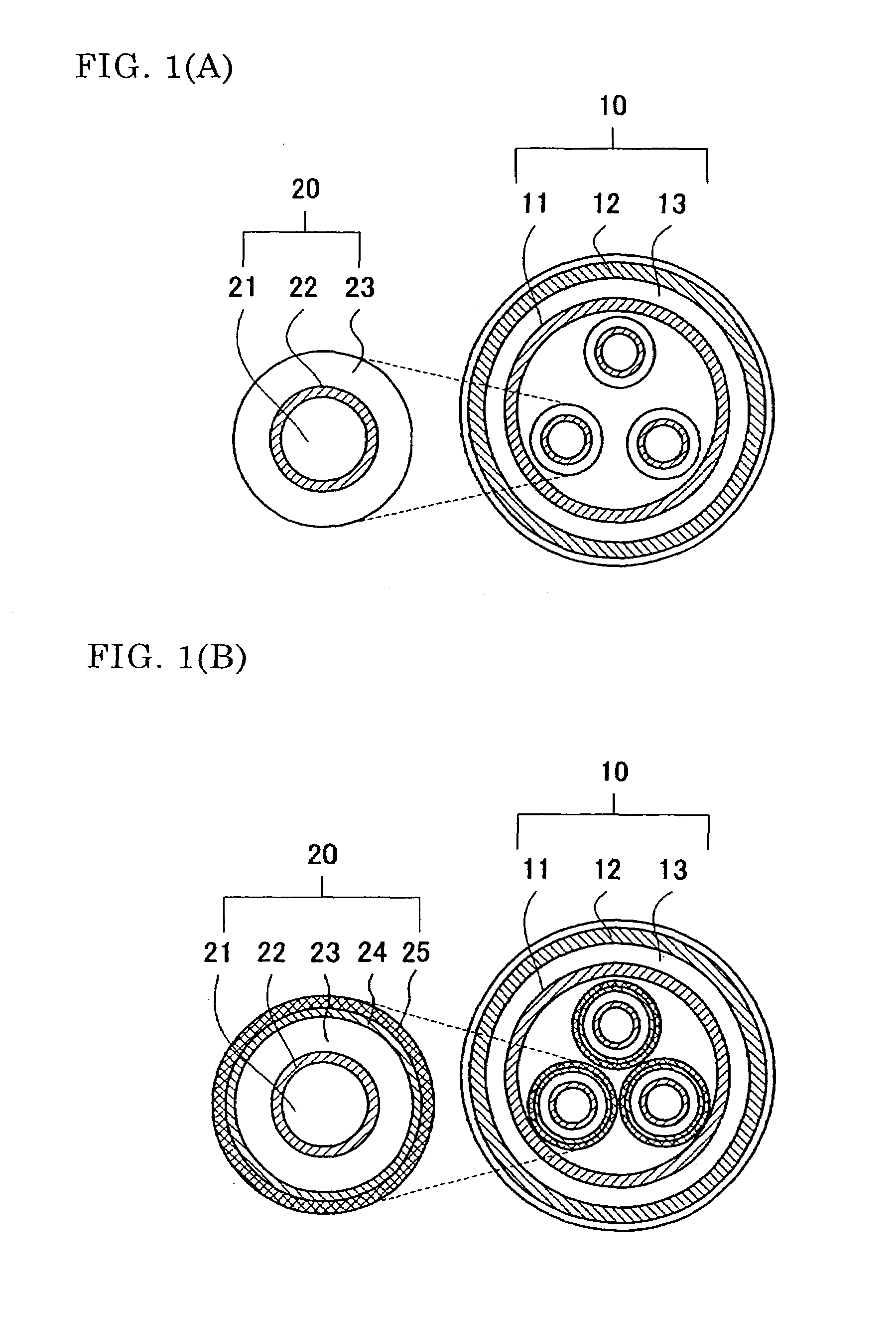
[0031]FIG. 1(A) is a sectional view illustrating a superconducting cable without a return-current conductor according to the present invention. FIG. 1(B) is a sectional view illustrating a superconducting cable with a return-current conductor according to the present invention.

[0032][Overall Structure]

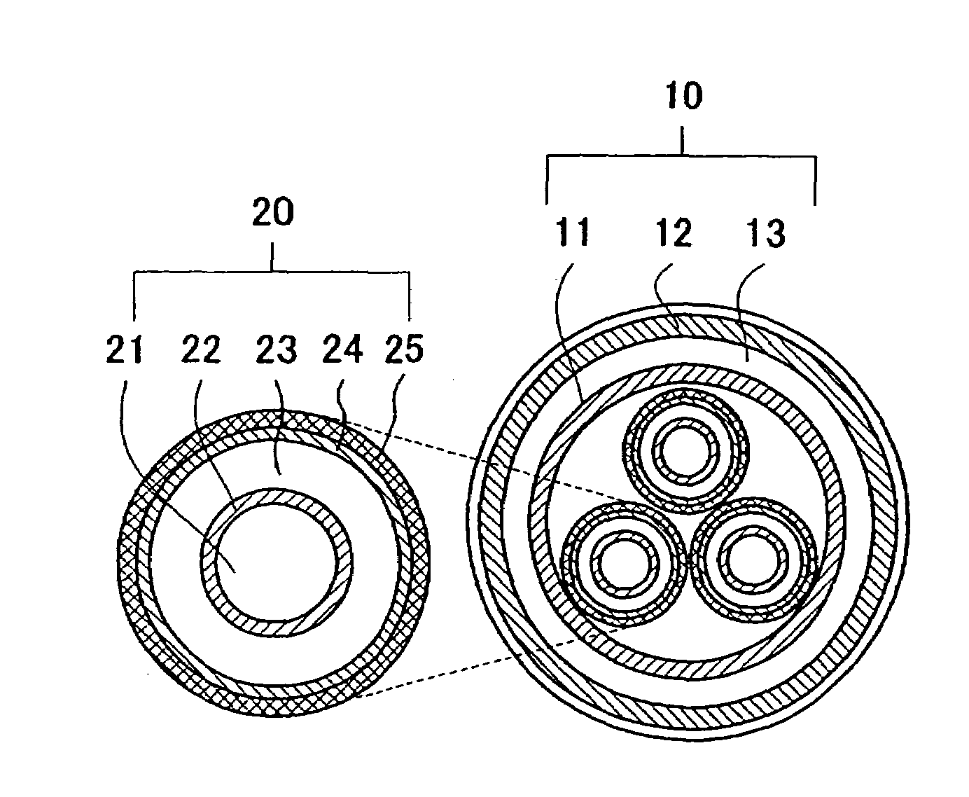
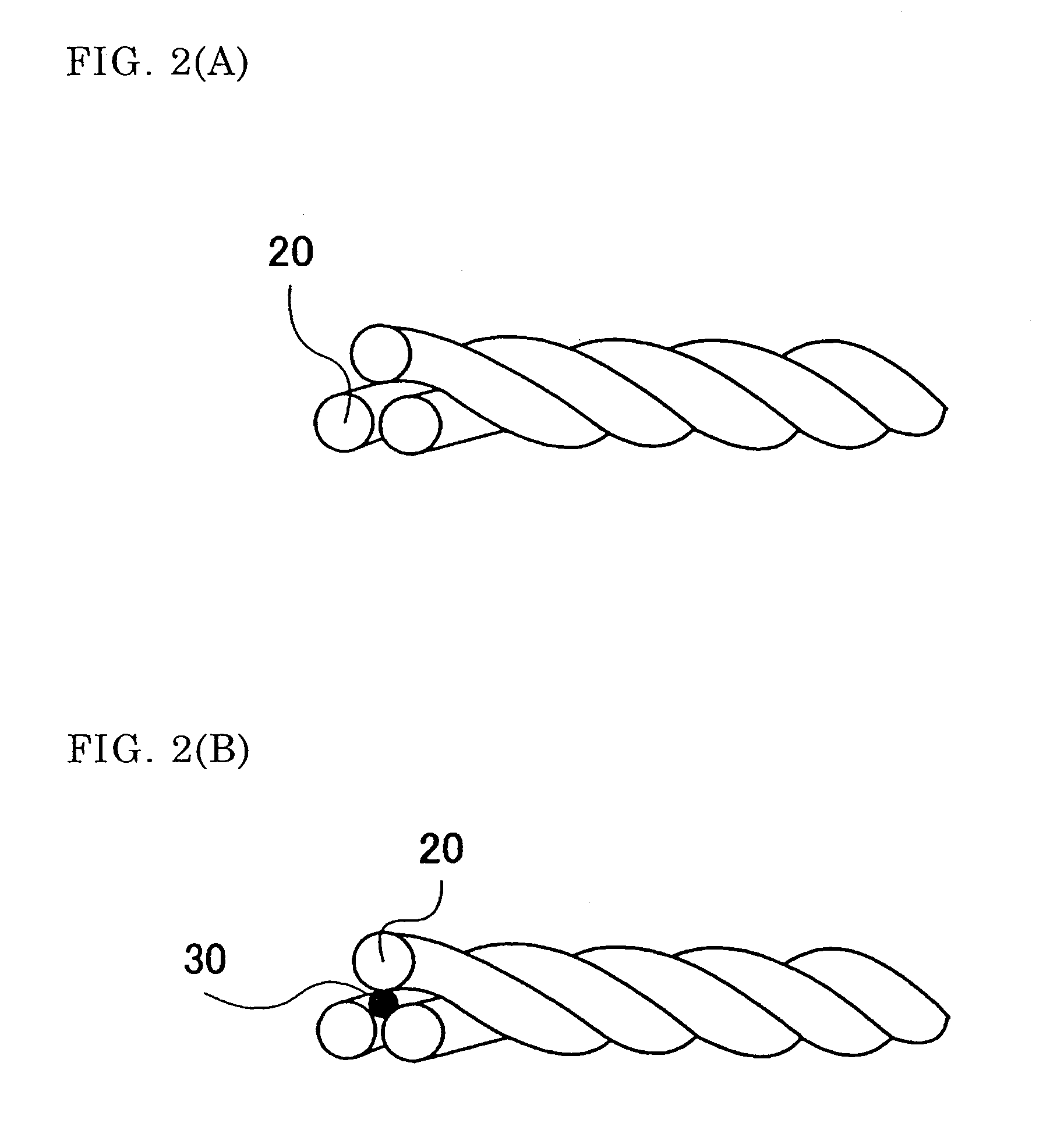
[0033]In this cable, three cable cores 20 are stranded together and are housed in a thermal insulation pipe 10.

[0034][Thermal Insulation Pipe]

[0035]The thermal insulation pipe 10 is a double pipe structure formed by an inner pipe 11 and an outer pipe 12. A vacuum thermal insulation layer 13 is disposed between the inner pipe 11 and the outer pipe 12. Within the vacuum thermal insulation layer, a laminated body formed of a plastic net and a metal foil, i.e., so-called “super insulation”, is disposed. A space formed between the inner side of the inner pipe 11 and the core 20 serves as a channel for a coolant, such as liquid n...


PUM

PropertyMeasurementUnit
superconductingaaaaaaaaaa
electricalaaaaaaaaaa
thermal contractionaaaaaaaaaa

Abstract

A DC superconducting cable which is formed by housing stranded three cable cores in a thermal insulation pipe and in which structure for absorbing thermal contraction occurring during cooling can easily be achieved by adjusting the stranded state of the cores. Also, the structure in which three cores are housed together in the thermal insulation pipe enables the simultaneous cooling of the three cores, allowing the cooling system to be simplified.

Description

TECHNICAL FIELD[0001]The present invention relates to direct current (DC) superconducting cables and DC superconducting cable lines. More particularly, the invention relates to a DC superconducting cable which allows easy implementation of measures against thermal contraction occurring during cooling.BACKGROUND ART[0002]Three-core high temperature superconducting cables (three-core HTS cables) are known as conventional alternating current (AC) superconducting cables (see, for example, Japanese Patent Application Publication Nos. 9-134620 and 2001-202837). In these cables, a three-core stranded unit is housed in a thermal insulation pipe. Each cable core is formed of, sequentially from the center, a former, a superconducting cable conductor, an electrical insulating layer, and a shielding layer. Generally, a space formed in the former and a space formed between the thermal insulation pipe and each cable core serve as coolant channels. The superconducting cable conductor is formed by ...

Claims


Application Information

Patent Timeline
Patent Type & Authority Patents(United States)
IPC IPC(8): H01B12/00H01B12/02H01B12/08H01B12/16
CPCH01B12/02Y02E40/641Y02E40/60H01B12/08H01B12/16
Inventor HIROSE, MASAYUKI
Owner SUMITOMO ELECTRIC IND LTD
Why Eureka
Try Eureka