Power supply branching control apparatus of electric load and method for supplying power to electric load

一种供电控制、电负载的技术,应用在电池电路装置、电路装置、紧急保护电路装置等方向,达到简化散热机构、节减使用个数的效果

Active Publication Date: 2014-09-03
MITSUBISHI ELECTRIC CORP
View PDF7 Cites 21 Cited by
  • Summary
  • Abstract
  • Description
  • Claims
  • Application Information

AI Technical Summary

Problems solved by technology

In contrast, according to Patent Document 2, a reverse polarity protection element and a power supply switching element are used as a set of switching elements, thereby solving the problem related to the reverse polarity of the power supply

Method used


Image

  • Power supply branching control apparatus of electric load and method for supplying power to electric load
  • Power supply branching control apparatus of electric load and method for supplying power to electric load
  • Power supply branching control apparatus of electric load and method for supplying power to electric load

Examples


Embodiment approach 1

[0031] (1) Detailed description of the structure

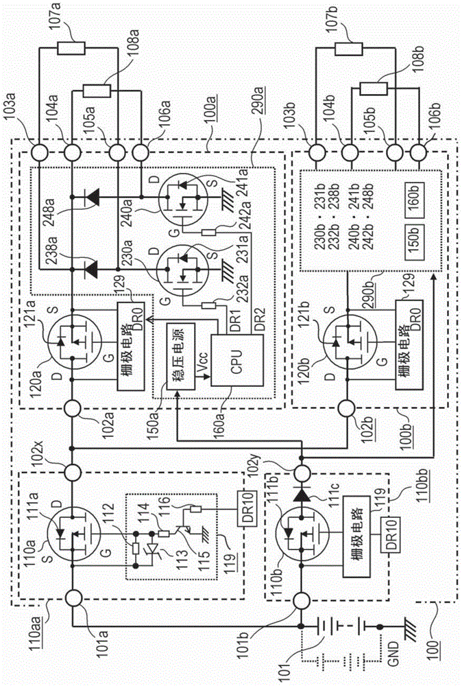
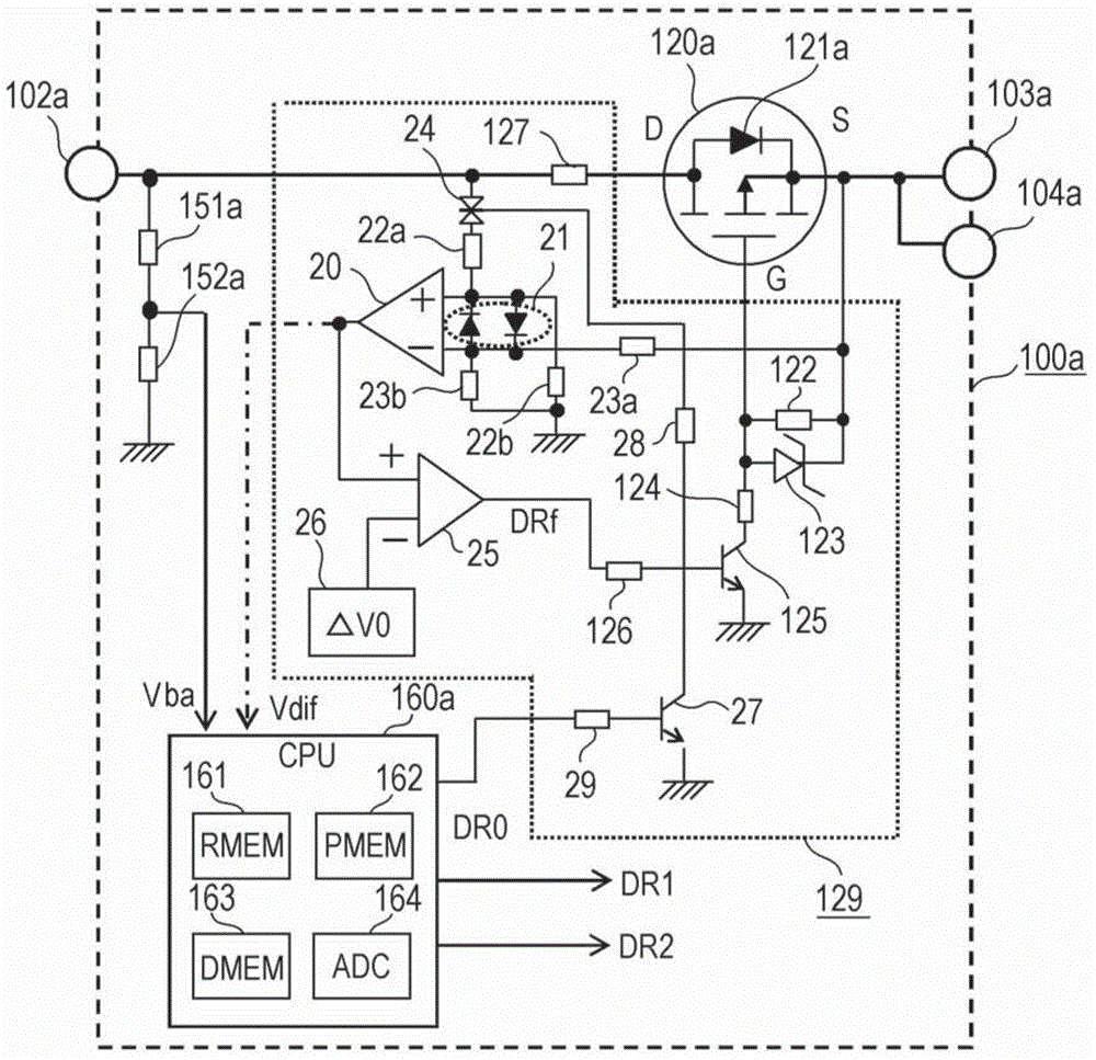
[0032] The overall circuit diagram showing the branch power supply control device of the electric load according to the first embodiment of the present invention is figure 1 , and with figure 1 The detailed control circuit diagram related to the gate control circuit section 129 is figure 2 , to describe its structure in detail. exist figure 1 Among them, the branch power supply control device 100 is powered by, for example, an in-vehicle battery that is a DC power supply 101, and includes: a power supply and distribution control device 110aa that divides and distributes a plurality of electrical loads; first and second branch power supply control devices 100a, 100b and a power supply control device 110bb for supplying power to the stabilized power supplies 150a and 150b provided in the first and second branch power supply control devices 100a and 100b. The first branch power supply control device 100a supplies power to...

Embodiment approach 2

[0054] (1) Detailed description of the structure

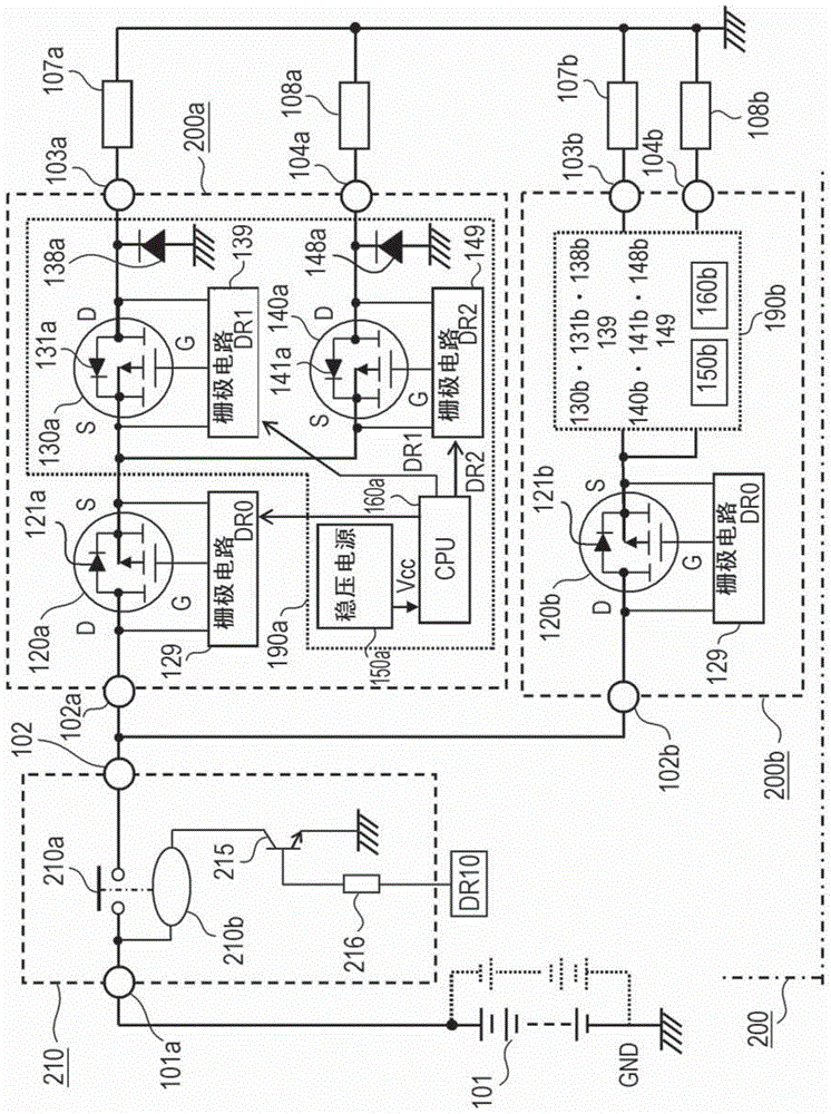
[0055] The overall circuit diagram showing the branch power supply control device of the electric load according to the second embodiment of the present invention is image 3 , and with image 3 The detailed control circuit diagram related to the switch gate control circuit section 139 is Figure 4 , with figure 1 The difference is centered on the structure, and its structure is explained in detail. Furthermore, as figure 1 and image 3 The first major difference in figure 1 In the power supply and distribution control device 110aa of the present invention, a P-channel field effect transistor is used as the power supply switching element 110a. image 3 In the power supply and distribution control device 210, the output contact of the electromagnetic relay is used as the power supply switch element 210a. Also, as a second major difference, figure 1 The load switching element is an N-channel type field effect transis...

Embodiment approach 3

[0077] (1) Detailed description of the structure

[0078] The overall circuit diagram showing the branch power supply control device of the electric load according to the third embodiment of the present invention is Figure 5 , and with Figure 5 The detailed control circuit diagram related to the gate control circuit section 329 and the switch gate control circuit sections 339 and 349 of Image 6 , Figure 7 , to describe its structure in detail. Furthermore, as figure 1 , image 3 The first major difference in figure 1 In the power supply and distribution control device 110aa of the present invention, a P-channel field effect transistor is used as the power supply switching element 110a. Figure 5 In the power supply and distribution control device 310, an N-channel field effect transistor is used as the power supply switching element 310a. Also, as a second major difference, figure 1 The first and second reverse connection protection elements 120a and 120b use P-c...


PUM


Abstract

The invention relates to a power supply branching control apparatus of an electric load and a method for supplying power to the electric load. Power supply current is supplied to a plurality of electric loads (107a,107b), the power supply current being generated by a DC power supply, flowing in and branching from a shared power supply switching device and then flowing in reverse connection protection devices that are a field-effect transistor and connected in series to the electric loads, respectively. The reverse connection protection devices are connected in a polarity such that the power supply current flows in the forward direction of parasitic diodes generated between the source terminal S and the drain terminal D of the field-effect transistor. When the current in the field-effect transistor is less than a predetermined value, a gate control circuit interrupts the gate voltage of the reverse connection protection device to cause the reverse connection protection device to open.

Description

technical field [0001] The invention relates to a branch power supply control device and a branch power supply control method for electric loads. A plurality of electric loads that supply power via a power supply switch element and a reverse connection protection element can share the power supply switch element, and branch and connect a plurality of reverse connection protection elements. . Background technique [0002] For example, in an on-vehicle electric load, a plurality of power supply switching elements are provided between a DC power supply serving as an on-vehicle battery and multiple on-vehicle electric loads, and one power supply switching element separately supplies power to one or more on-vehicle electric loads. For example, according to Patent Document 1 "Power Distribution Device for Vehicles" Image 6 , using an intelligent power switch, that is, a field effect transistor 44A, as a power supply switching element to replace the output contact of the electroma...

Claims


Application Information

Patent Timeline
Patent Type & Authority Applications(China)
IPC IPC(8): H02J7/00H02H11/00
CPCH02J7/0034H02J1/00Y10T307/25H03K17/00H02H11/003H02H1/00H02H11/002
Inventor 神崎将造桥本光司木村友博
Owner MITSUBISHI ELECTRIC CORP
Why Eureka
Try Eureka