Uniaxial drive unit and surface shape measuring apparatus using the same

a drive unit and surface shape technology, applied in the direction of using mechanical means, mechanical measuring arrangements, instruments, etc., can solve the problems of large vibration at the time of high-speed movement, low movement speed of a detector, and inability to perform high-speed movement, etc., to achieve the capability of low vibration driving, no worn parts, and wide speed range

Inactive Publication Date: 2007-07-03
TOKYO SEIMITSU
View PDF11 Cites 12 Cited by
  • Summary
  • Abstract
  • Description
  • Claims
  • Application Information

AI Technical Summary

Benefits of technology

[0033]According to the present invention, the surface shape measuring apparatus is driven by the above-described uniaxial drive unit. Therefore, advantageous effects, which are characteristic of the linear motor used for the uniaxial drive unit, of no maintenance, no worn parts, capability of low-vibration driving, wide speed range, high rigidity, simple construction, no backlash, etc. can be achieved.
[0034]The surface shape measuring apparatus means an apparatus for measuring the surface shape of an object under test by relatively moving the detecting section along the surface of the object under test, which is represented by a surface roughness measuring apparatus, contour measuring apparatus, roundness measuring apparatus, three-dimensional coordinate measuring apparatus, and the like, and also includes an apparatus for measuring not only the outer surface of an object but also, for example, the inner peripheral surface of a cylindrical object.
[0035]As the detecting section, a contact type detecting section is generally used which makes measurement while a probe is brought into contact with the surface of an object under test. However, the detecting section is not limited to this type, and includes a non-contact type detecting section such as a laser type detecting section.
[0036]As described above, according to the present invention, the driving section provided so as to be slidable in the uniaxial direction with respect to the unit body is driven by the linear motor via the winding motion transmission member. By using this configuration, the driving section can be separated from the linear motor through a predetermined distance. As a result, the problem in that a dimensional error of the whole of unit occurs due to the heat generated in the linear motor can be solved.
[0037]Also, according to the present invention, the surface shape measuring apparatus is driven by the above-described uniaxial drive unit. Therefore, advantageous effects, which are characteristic of the linear motor used for the uniaxial drive unit, of no maintenance, no worn parts, capability of low-vibration driving, wide speed range, high rigidity, simple construction, no backlash, etc. can be achieved.

Problems solved by technology

On the other hand, in a surface shape measuring apparatus, the above-described conventional linear driving mechanism has problems as described below, and the improvement thereof has been demanded.
Specifically, a surface roughness measuring apparatus, contour measuring apparatus, roundness measuring apparatus, and three-dimensional coordinate measuring apparatus have a problem in that the movement speed of a detector is low, and hence high-speed movement cannot be performed.
Also, the surface roughness measuring apparatus, contour measuring apparatus, and roundness measuring apparatus have a problem in that vibrations at the time of high-speed movement is large.
The surface roughness measuring apparatus and contour measuring apparatus have a problem in that the construction is complicated, and a highly accurate gear-to-gear pitch dimension is required.
Also, the three-dimensional coordinate measuring apparatus has a problem in that high-speed movement cannot be performed because a wire is used.

Method used


Image

  • Uniaxial drive unit and surface shape measuring apparatus using the same
  • Uniaxial drive unit and surface shape measuring apparatus using the same
  • Uniaxial drive unit and surface shape measuring apparatus using the same

Examples


first embodiment

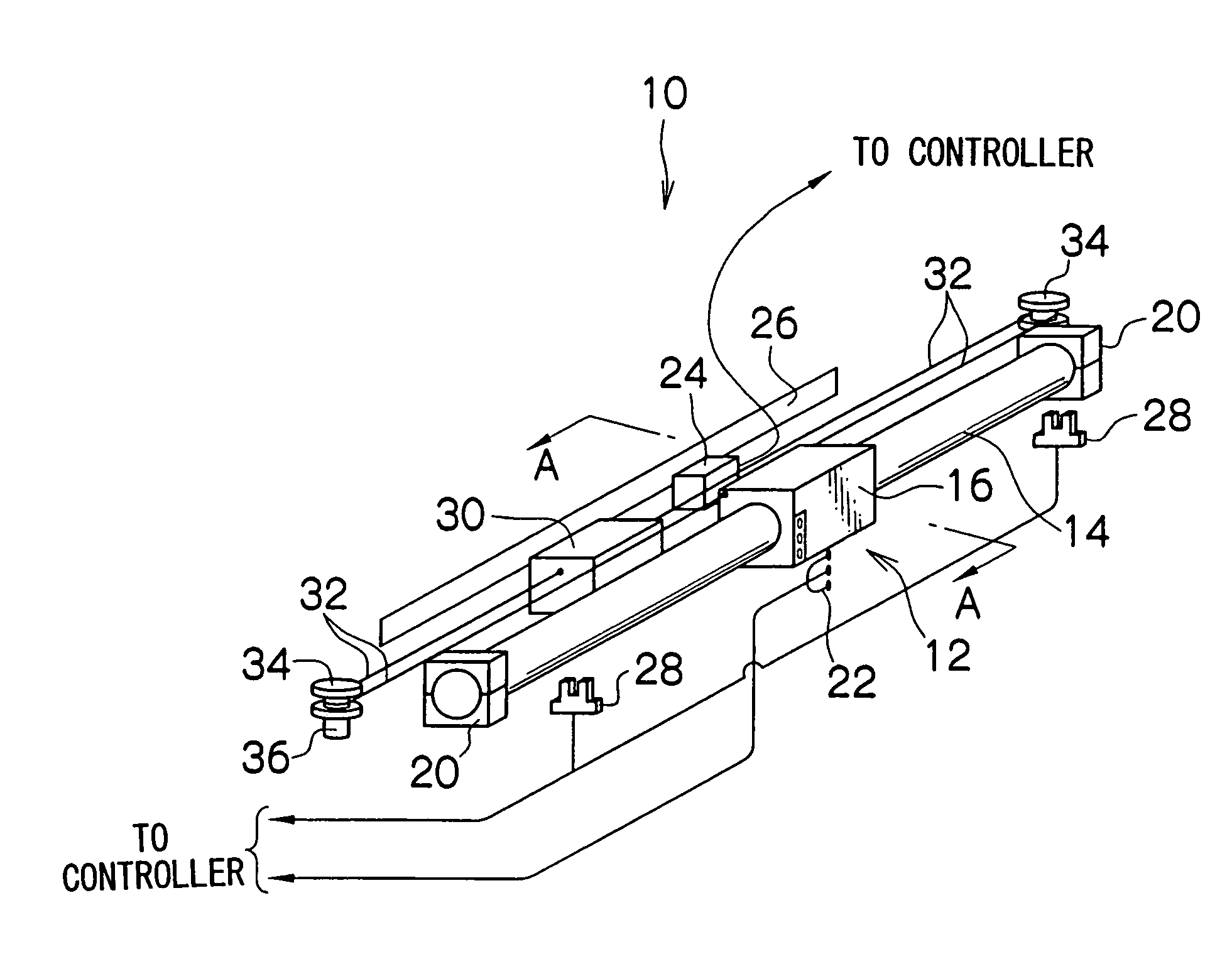
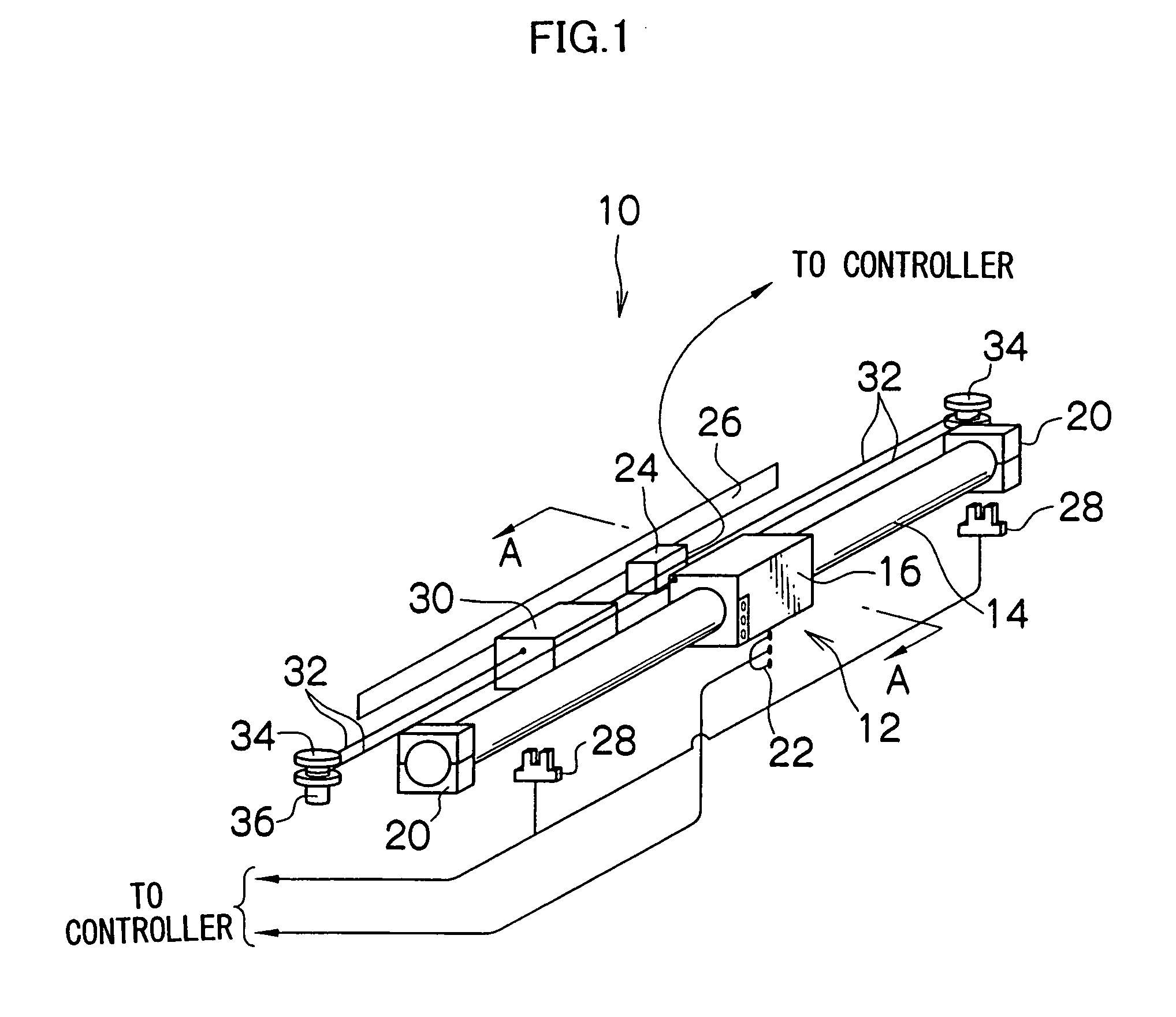
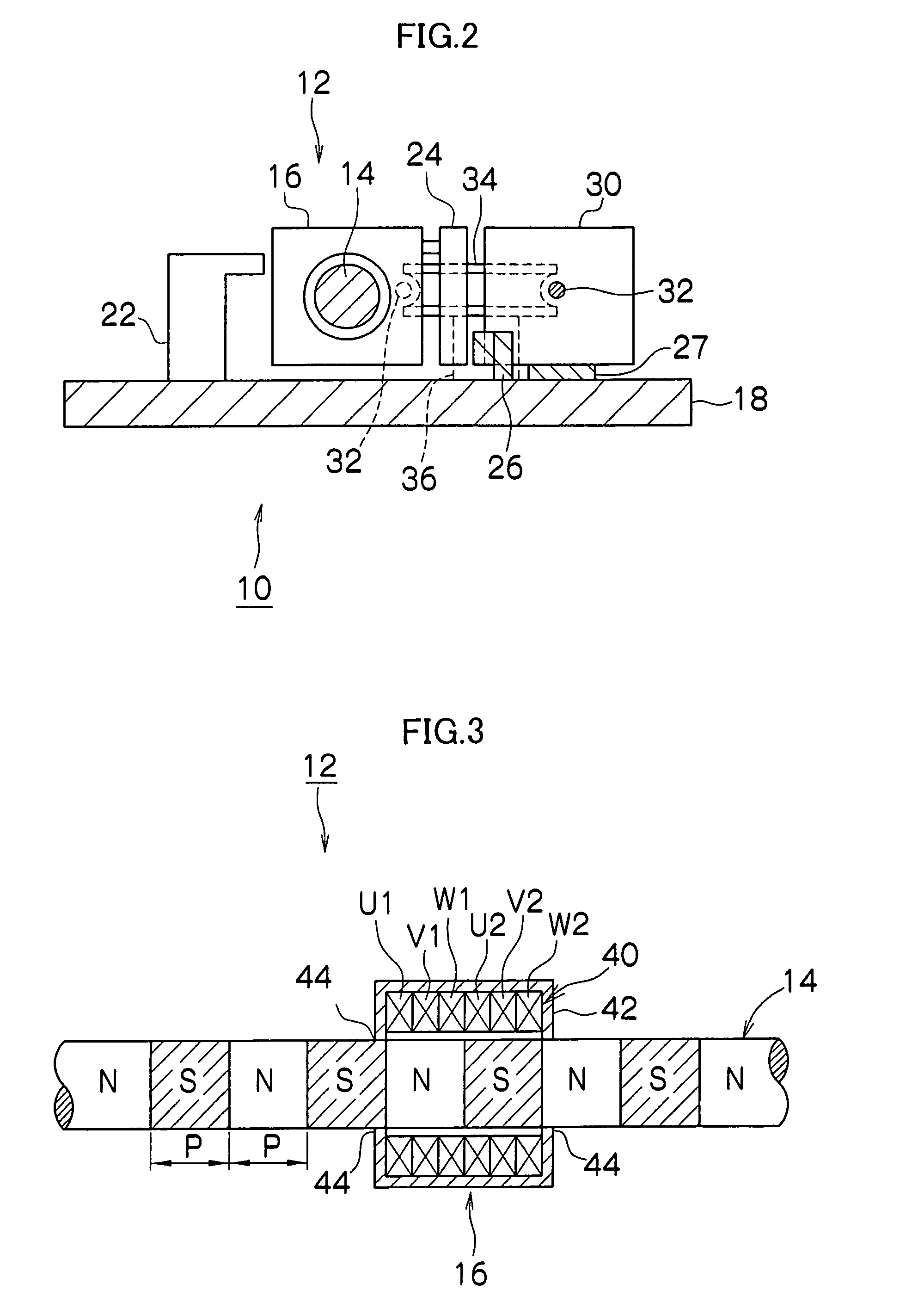
[0053]a uniaxial drive unit in accordance with the present invention will now be described in detail with reference to the accompanied drawings. FIG. 1 is a general perspective view schematically showing a uniaxial drive unit 10 in accordance with the present invention. FIG. 2 is a sectional view taken along the line A—A of FIG. 1, and FIG. 3 is an enlarged sectional view of an essential portion of a linear motor 12.

[0054]The uniaxial drive unit 10 is made up of a linear motor 12 mainly comprising a fixed part 14 and a moving part 16, a base plate 18 (not shown in FIG. 1), which is a unit body for fixing the elements, fixing members 20, 20 for fixing both ends of the fixed part 14 to the base plate 18, a cable bare 22 for supplying electric power to the moving part 16, an encoder 24 for detecting the position in the uniaxial direction of the moving part 16 and an encoder scale 26, limit sensors 28, 28 which are provided near both ends of the fixed part 14 to detect an end limit of t...

second embodiment

[0068]Next, a preferred embodiment (a second embodiment) of a surface roughness measuring apparatus, which is one example of a surface shape measuring apparatus using the uniaxial drive unit in accordance with the present invention, will be described in detail with reference to the accompanied drawings. FIG. 4 is a perspective view showing the whole of a surface roughness measuring apparatus 100 in accordance with the embodiment, and FIG. 5 is a block diagram showing a-configuration of the surface roughness measuring apparatus 100 shown in FIG. 4.

[0069]The surface roughness measuring apparatus 100 includes a measuring section (data output device) 112, a data processing unit 114, an input device (for example, a keyboard, a mouse: measurement region designating device, setting device) 116, a monitor 118, and a roughness output device 136. The measuring section 112 has a pickup 122 for measuring the surface roughness of a work W, shown in FIG. 5, mounted on a measurement bed 120, and t...

third embodiment

[0087]Next, a preferred embodiment (a third embodiment) of a-roundness measuring apparatus, which is another example of the surface shape measuring apparatus in accordance with the present invention, will be described in detail with reference to the accompanied drawings. FIG. 10 is a perspective view showing the whole of a roundness measuring apparatus 210 in accordance with this embodiment. The roundness measuring apparatus 210 includes an apparatus body 212, a Z-direction moving device 214 provided on the right-hand side on the apparatus body 212, an X-direction moving device 216 supported on the Z-direction moving device 214, a detector holder 222 which is supported by the left end portion of the X-direction moving device 216 so as to be turnable around the X axis, a detector 224 supported by the tip end portion of the detector holder 222 so as to be turnable, a work table 218 provided substantially in the center on the upper surface of the apparatus body 212, and a control panel...


PUM


Abstract

There is provided a uniaxial drive unit using a linear motor having a fixed part which is a rod-shaped magnet fixed to a unit body and formed so that the N poles and the S poles are arranged alternately; and a moving part which is a ring-shaped member having a coil member, fitted on the fixed part, and capable of moving along the fixed part. A driving section provided so as to be slidable in the uniaxial direction with respect to the unit body is connected to the moving part or a balance weight fixed to the moving part by a winding motion transmission member via a winding motion transmitting support member provided near one end or both ends of the unit body.

Description

BACKGROUND OF THE INVENTION[0001]1. Field of the Invention[0002]The present invention relates to a uniaxial drive unit and a surface shape measuring apparatus using the unit. More particularly, it relates to a uniaxial drive unit using a linear motor in a driving section and a surface shape measuring apparatus using the unit.[0003]2. Description of the Related Art[0004]As a linear motor capable of being used for a uniaxial drive unit, linear motors having various configurations have conventionally been known. Among these, a linear motor having a fixed part, which is a rod-shaped magnet, and a moving part, which is a ring-shaped member fitted on the fixed part, having a coil member, and being capable of moving linearly along the fixed part, has features of less cogging, less unevenness of speed, and the like, and hence has been coming onto the market (for example, trade name: SHAFT MOTOR, manufactured by GMC HILLSTONE Co., Ltd.).[0005]Also, as an improved technology for such a linear...

Claims


Application Information

Patent Timeline
Patent Type & Authority Patents(United States)
IPC IPC(8): H02K41/00G01B5/004G01B21/30G01B5/20H02K41/02H02K41/03
CPCG01B5/004G01B5/20H02K41/031
Inventor MIYAMOTO, HIROSHI
Owner TOKYO SEIMITSU
Why Eureka
Try Eureka