Pointing device and portable information terminal using the same

a technology of portable information terminal and pointing device, which is applied in the direction of static indicating devices, instruments, television systems, etc., can solve the problems of limiting the size reduction, requiring more operations, and unable to meet the demand

Inactive Publication Date: 2007-07-03
MAXELL HLDG LTD
View PDF8 Cites 35 Cited by
  • Summary
  • Abstract
  • Description
  • Claims
  • Application Information

AI Technical Summary

Benefits of technology

[0007]It is an object of the present invention to provide a pointing device capable of being small-sized and facilitating movement of the pointer, and a portable information terminal using such a pointing device.

Problems solved by technology

For the track ball or dial type pointing device above, meeting this demand is difficult because this pointing device includes a physical movable section such as a ball or disk, which puts a limit to reduction of the size.
With the pointing device such as the cross pointer and stick pointer above, the pointer basically moves one step by one operation, that is, the pointer moves by one item displayed on the display screen at a time, and therefore selecting an item at a considerable distance on the display screen requires more operations, which takes time and trouble.
Moreover, the track pad described above moves the pointer by touching the sensor plate with the finger and therefore the sensor plate must have an area sufficiently greater than the area of the finger that touches this and is not suited to miniaturization.

Method used


Image

  • Pointing device and portable information terminal using the same
  • Pointing device and portable information terminal using the same
  • Pointing device and portable information terminal using the same

Examples


Embodiment Construction

[0045]With reference now to the attached drawings, embodiments of the present invention will be explained below.

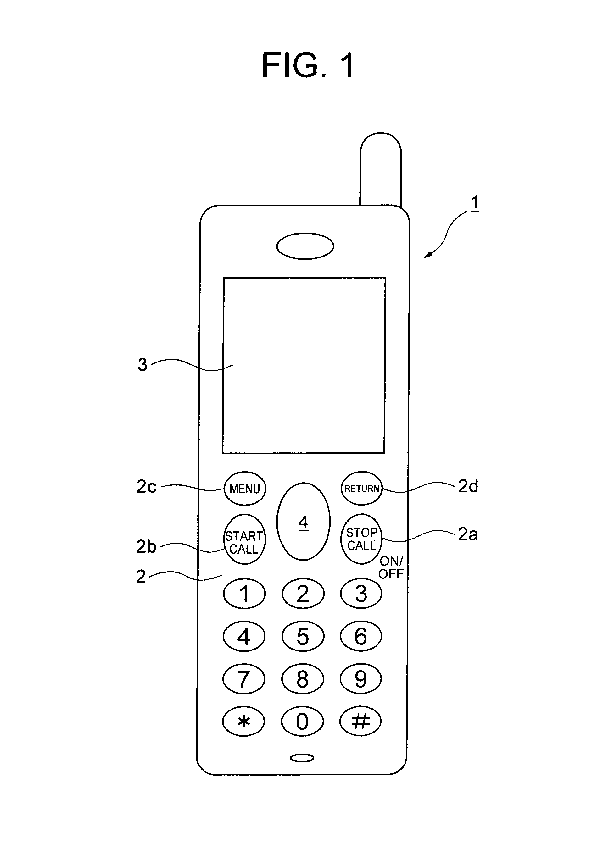
[0046]FIG. 1 is a front view showing an embodiment of a portable information terminal using a pointing device according to the present invention. Reference numeral 1 denotes a portable information terminal; 2, an operation panel; 2a, a “Power / stop call” button; 2b, “Start call” button; 2c, a “Menu” button; 2d, a “Return” button; 3, a display screen; 4, a pointing device. Here, this embodiment shows a case of a cellular phone, but this embodiment can also be other portable information terminals such as a portable type personal computer.

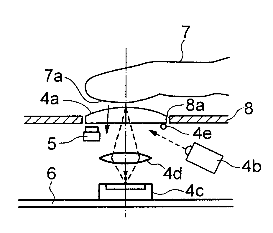
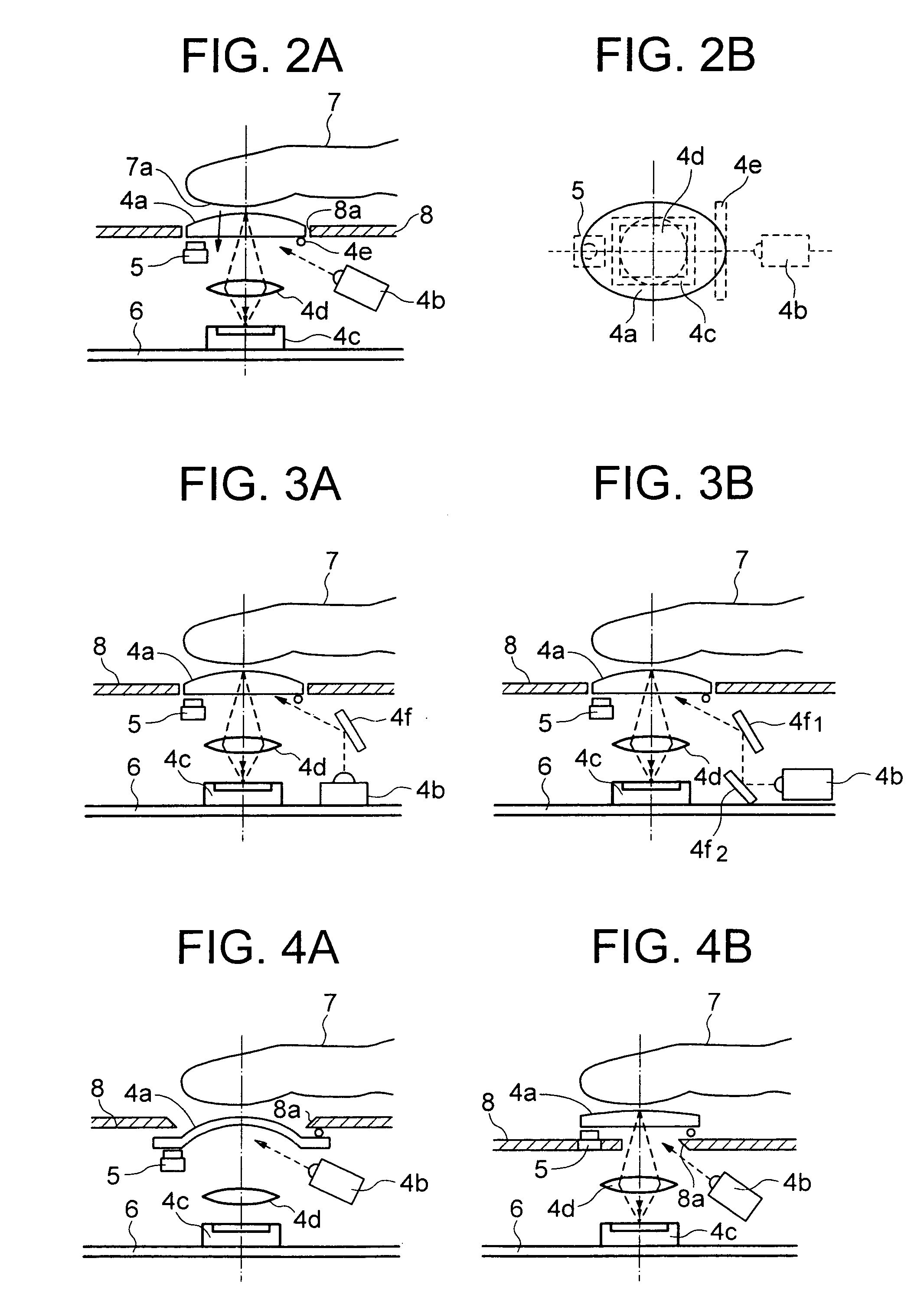
[0047]In the same drawing, the operation panel 2 including various operation components such as the pointing device 4 and the display screen 3 that shows an image and pointer (cursor, not shown) are provided on the front of the portable information terminal 1. The operation panel 2 is provided with the “Power / stop call” button 2a to indicate ...


PUM


Abstract

A pointing device is placed in a through hole provided on an outer case of the portable information terminal. The portable information terminal includes a fingerplate attached to a through hole via a hinge 4e; an image pick-up element placed on a circuit board; a condensing lens that forms an image on an outer surface of the fingerplate on an image pick-up plane of the image pick-up element; and a light emitting device that irradiates the outer surface of the fingerplate with illumination light, and takes the image of a pattern such as a fingerprint of a fingertip that touches the outer surface of the fingerplate by using the image pick-up element. When the fingertip moves while touching the fingerplate, the image taken by the image pick-up element changes and the pointer displayed on a display screen is moved in a direction according to a change direction and by a distance corresponding to a quantity of change.

Description

BACKGROUND OF THE INVENTION[0001]The present invention relates to a pointing device for moving a pointer (cursor) on a display screen used for a portable information terminal such as a cellular phone, and a portable information terminal using the pointing device.[0002]Conventionally, a portable information terminal such as a portable type personal computer and cellular phone has an operation panel provided with a display screen on which a pointer for pointing to a desired position of an image is displayed and a pointing device for moving this pointer to a desired position.[0003]As such a conventional pointing device, a track ball that moves a pointer by detecting the rotation of a ball and a dial type pointer that moves a pointer by detecting the rotation of a disk are known. Furthermore, as portable information terminals are being increasingly implemented with multi-functions and large-sized display screen, and in order to make it possible to arbitrarily and smoothly select more se...

Claims


Application Information

Patent Timeline
Patent Type & Authority Patents(United States)
IPC IPC(8): G09G5/00G06F3/042G06F3/033G06F3/0354G06F3/038G06F3/041H04M1/247H04N5/225
CPCG06F3/0338G06F3/0421
Inventor HOSHINO, TAKESHIMARUYAMA, YUKINOBUASADA, YUKINORI
Owner MAXELL HLDG LTD
Why Eureka
Try Eureka