Transflective liquid crystal display

a liquid crystal display and transmissive technology, applied in non-linear optics, instruments, optics, etc., can solve the problems of high power consumption, complex structure, and ineffective light conversion of transmissive lcd, and achieve the effect of achieving the effect of equal light efficiency

Inactive Publication Date: 2007-07-03
INNOLUX CORP
View PDF7 Cites 14 Cited by
  • Summary
  • Abstract
  • Description
  • Claims
  • Application Information

AI Technical Summary

Benefits of technology

[0010]The present invention is to solve the above-mentioned problem and provide an array substrate for a transflective liquid crystal display device. The array substrate of the present invention can produce a single cell gap transflective liquid crystal display device having substantially equal light efficiency for both reflection and transmission regions.

Problems solved by technology

However, the transmissive LCD is a non-effective light converter that merely transmits about 3% to 8% of light from the backlight.
Therefore, the transmissive LCD requires a backlight device having high brightness, leading to high power consumption.
However, the reflective LCD can be used during the day or in environments where external light exists, but not during the night or under poor ambient lighting.
Thus, both R and T can have equally high efficiency of 100% as shown in FIG. 2b. This approach, however, leads to much more complicated structure.
It is unclear how commercially viable would be the disclosed structure.

Method used


Image

  • Transflective liquid crystal display
  • Transflective liquid crystal display
  • Transflective liquid crystal display

Examples


first embodiment

[0027]FIG. 3 is a plan view of a pixel of a transflective liquid crystal display panel according to the present invention. FIG. 4a is a cross-section taken along line 4-4 of FIG. 3. Referring to FIGS. 3 and 4a, the transflective LCD panel includes an array substrate S1 and an opposing substrate 20 spaced apart from the array substrate S1. The array substrate S1 includes a substrate 10, a plurality of scanning lines (SL, gate lines), a plurality of data lines (DL), a reflector 12, a transmissive electrode 14, and a planarization layer 16 formed between the reflector 12 and the transmissive electrode 14. The opposing substrate 20 has a common electrode 22 below it. A liquid crystal layer 30 is interposed between the transmissive electrode 14 and the common electrode 22.

[0028]Scanning lines (SL) extend along an X axis, data lines (DL) extend along a Y axis, and they cross each other to define a plurality of pixel regions. The pixel region includes a transmission region T and a reflecti...

second embodiment

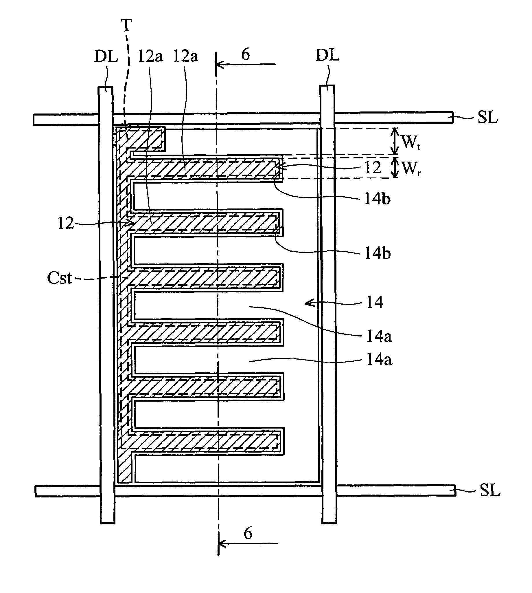
[0035]FIG. 5 is a plan view of a pixel of a transflective liquid crystal display panel according to the present invention. FIG. 6a is a cross-section taken along line 6-6 of FIG. 5. Referring to FIGS. 5 and 6a, the transflective LCD panel includes an array substrate S2 and an opposing substrate 20 spaced apart from the array substrate S2. The array substrate S2 includes a substrate 10, a plurality of scanning lines (SL, gate lines), a plurality of data lines (DL), a reflector 12, a transmissive electrode 14 located in the same level as the reflector 12, a storage capacitor Cst, and a planarization layer 16 formed between the reflector 12 and the storage capacitor Cst. The opposing substrate 20 has a common electrode 22 below it. A liquid crystal layer 30 is interposed between the transmissive electrode 14 and the common electrode 22.

[0036]Scanning lines (SL) extend along an X axis, data lines (DL) extend along a Y axis, and they cross each other to define a plurality of pixel region...


PUM

PropertyMeasurementUnit
widthaaaaaaaaaa
tilt angleaaaaaaaaaa
width Wraaaaaaaaaa

Abstract

An array substrate for a transflective liquid crystal display device is disclosed. The array substrate includes a substrate; a plurality of scanning lines and data lines on the substrate, crossing each other to define a plurality of pixel regions; a transmissive electrode disposed in the transmission region; and a reflector disposed in the reflection region and not subjected to a voltage. A lateral field is generated in the reflection region. The transflective LCD of the present invention achieves the maximum light efficiency in both reflection and transmission modes.

Description

BACKGROUND OF THE INVENTION[0001]1. Field of the Invention[0002]The present invention relates to transflective liquid crystal displays, and more particularly to single cell gap type transflective liquid crystal displays.[0003]2. Description of the Prior Art[0004]Liquid crystal display (LCD) types are divided into three kinds: a transmissive LCD, a reflective LCD, and a transflective LCD. However, the transmissive LCD is a non-effective light converter that merely transmits about 3% to 8% of light from the backlight. Therefore, the transmissive LCD requires a backlight device having high brightness, leading to high power consumption. The reflective LCD uses ambient light for imaging, thus saving power consumption. However, the reflective LCD can be used during the day or in environments where external light exists, but not during the night or under poor ambient lighting.[0005]Therefore, the transflective LCD has been introduced. In general, two main approaches of transflective LCD ha...

Claims


Application Information

Patent Timeline
Patent Type & Authority Patents(United States)
IPC IPC(8): G02F1/1335G02F1/1343
CPCG02F1/133555G02F2001/134381G02F1/134381
Inventor CHANG, WEI-CHIHCHUANG, LI-SEN
Owner INNOLUX CORP
Why Eureka
Try Eureka