Operator location tracking for remote control rail yard switching

a technology of operator location and switch, which is applied in the direction of process and machine control, instruments, navigation instruments, etc., can solve the problems of not being able to move efficiently and efficiently a switchman

Active Publication Date: 2007-07-03
GE GLOBAL SOURCING LLC
View PDF19 Cites 58 Cited by
  • Summary
  • Abstract
  • Description
  • Claims
  • Application Information

AI Technical Summary

Problems solved by technology

However, switch lists are not typically organized so as to address the switch locations in the rail yard, nor the efficient movement of a switchman among these locations to control the switches.

Method used


Image

  • Operator location tracking for remote control rail yard switching
  • Operator location tracking for remote control rail yard switching

Examples


Embodiment Construction

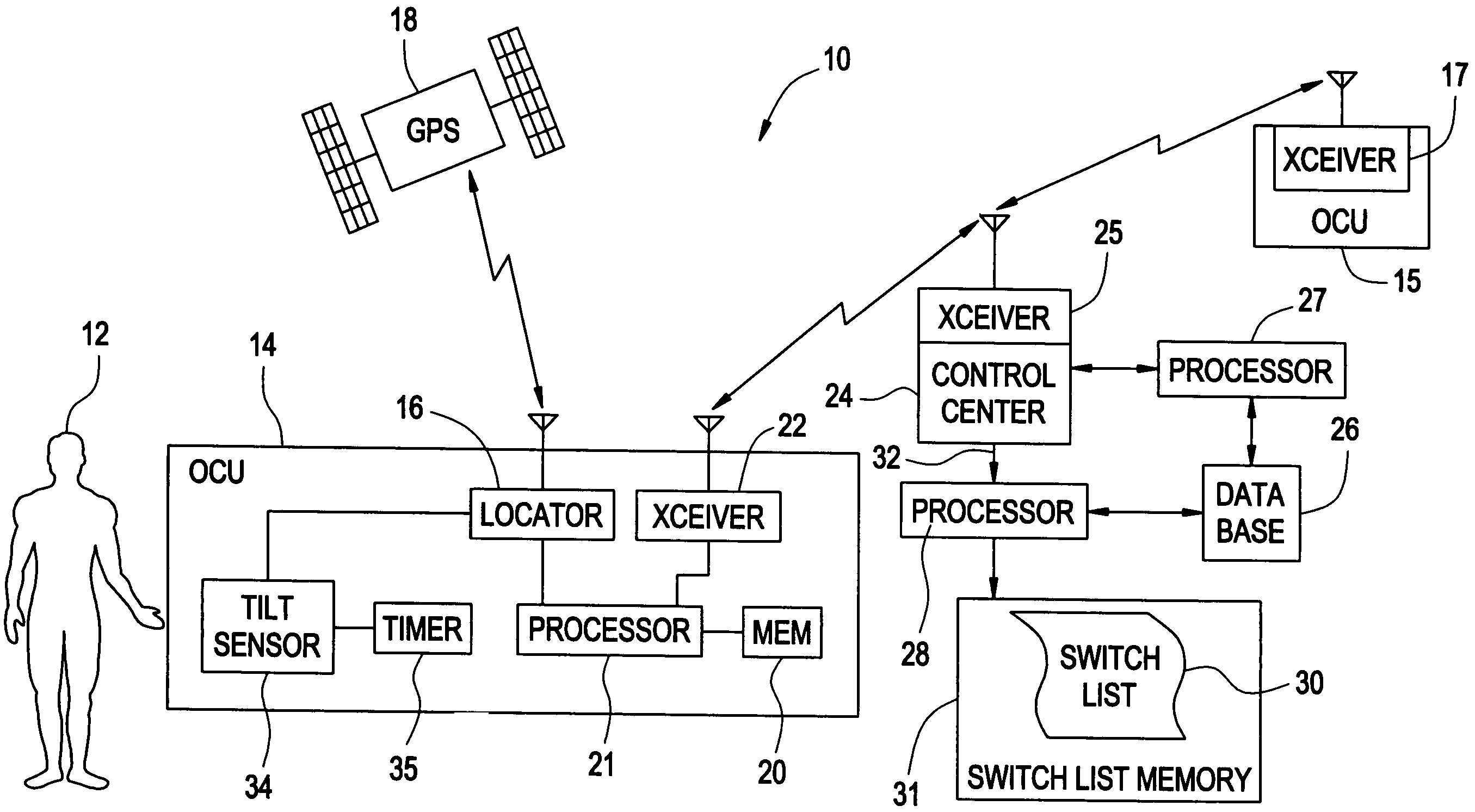
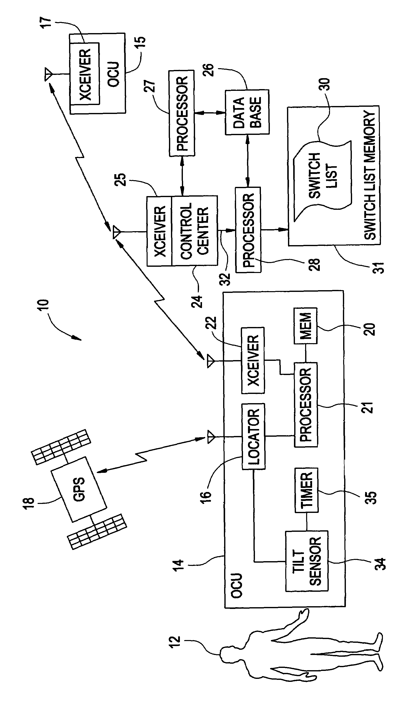
[0006]Prior art rail yard switching schemes employing switch lists have failed to account for movement of the switchman throughout the rail yard to effect the desired train movement. Because some rail yards may encompass one a square mile of more of track switching area, switching sequences need to be organized to have efficient movement of the switchman throughout the yard. Switching sequences for a certain switch list may vary from switchman to switchman, with many sequences being inefficient and unnecessarily time consuming and burdensome. Experienced switchmen may be able to formulate switching sequences based on a certain switch list that results in reduced movement of the switchman throughout the yard and thus reduce switching times by reducing the need for the switchman to traverse long distances between switches in a switch sequence.

[0007]The inventor of the present invention has innovatively recognized that by tracking an efficient switchman's locations and movements in a s...


PUM


Abstract

A system (10) for generating a rail yard switch list (e.g., 30) of switch positioning activities for efficient movement of a railyard operator (12). The system includes a first operator control unit (14) (OCU) having a locator (16) for determining a location of the OCU and an associated operator using the OCU during rail yard switching activities. The system also includes a first processor (28) for correlating the rail yard switching activities with a respective location of the OCU in the rail yard to establish a knowledge base of respective preferred locations in the rail yard, and a memory (e.g. 26) for storing the knowledge base of preferred locations in the railyard. The system further includes a second processor (27) for receiving a request (32) for a switch list, accessing the memory, and processing the request based on the knowledge base to generate a switch list.

Description

RELATED APPLICATIONS[0001]This application claims priority to U.S. Provisional Application Ser. No. 60 / 555,112 filed on Mar. 22, 2004, and incorporated herein by reference.FIELD OF THE INVENTION[0002]This invention relates to the field of remotely controlled locomotives, and, in particular, to tracking a location of an operator using a remote control system operator control unit (OCU) in a rail yard.BACKGROUND OF THE INVENTION[0003]Rail yards are used in the rail transportation environments to sort freight cars onto different track sections depending on each freight car's destination after leaving the yard. Yard switching refers to the transfer of a freight car or freight cars from one track to another, typically with the intent of assembling a train bound for a common destination designated for cars attached to the train for departure from the rail yard. In the past, switching of trains in a switchyard required a “switchman” on the ground at each end of the train to properly align ...

Claims


Application Information

Patent Timeline
Patent Type & Authority Patents(United States)
IPC IPC(8): B61L3/02B61L17/00B61L3/12
CPCB61L3/127B61L17/00B61L2205/04
Inventor PELTZ, DAVID MICHAEL
Owner GE GLOBAL SOURCING LLC
Why Eureka
Try Eureka