Selective promotion for resolution enhancement techniques

a technology of enhancement and promotion, applied in the field of system and method management of pattern data, can solve the problems of destroying the many advantages of hierarchy, causing only partially promoted polygons to be cut, and causing them to be distorted

Inactive Publication Date: 2007-07-03
SIEMENS PROD LIFECYCLE MANAGEMENT SOFTWARE INC
View PDF9 Cites 57 Cited by
  • Summary
  • Abstract
  • Description
  • Claims
  • Application Information

AI Technical Summary

Problems solved by technology

In particular, as the size and / or spacing between objects becomes smaller than the wavelength of light used for photolithographic patterning, a variety of optical distortions occur.
This flattening, however, makes a very large database representation for the microdevice, and destroys the many advantages that hierarchy brings.
However, as usually implemented, selective promotion can force polygons that are only partly promoted to be cut.
The introduction of these points of scission can be very awkward for many computations used to calculate RET effects.

Method used


Image

  • Selective promotion for resolution enhancement techniques
  • Selective promotion for resolution enhancement techniques
  • Selective promotion for resolution enhancement techniques

Examples


Embodiment Construction

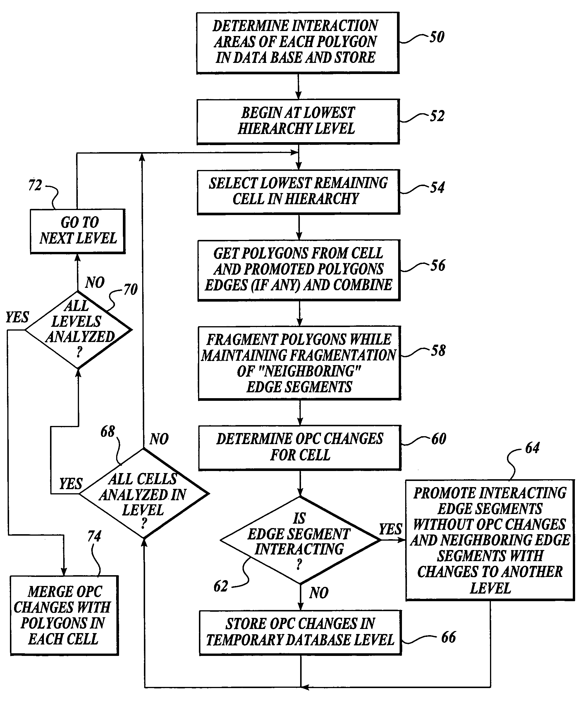
[0028]As indicated above, the present invention is a method and apparatus for selectively promoting polygons in a hierarchical database to facilitate the application of one or more Resolution Enhancement Techniques (RETs), and in particular to facilitate the application of Optical and Process Correction (OPC) techniques.

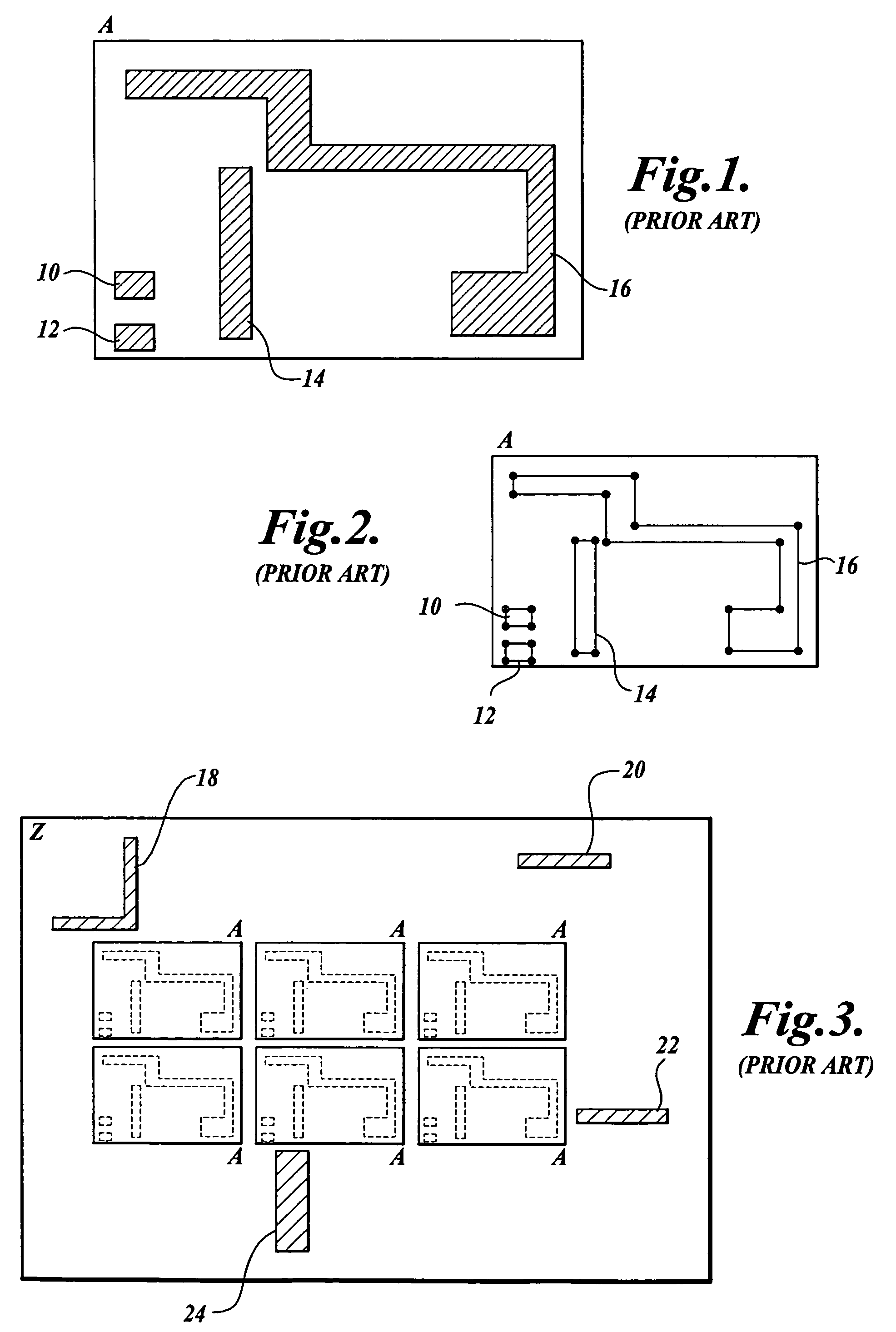
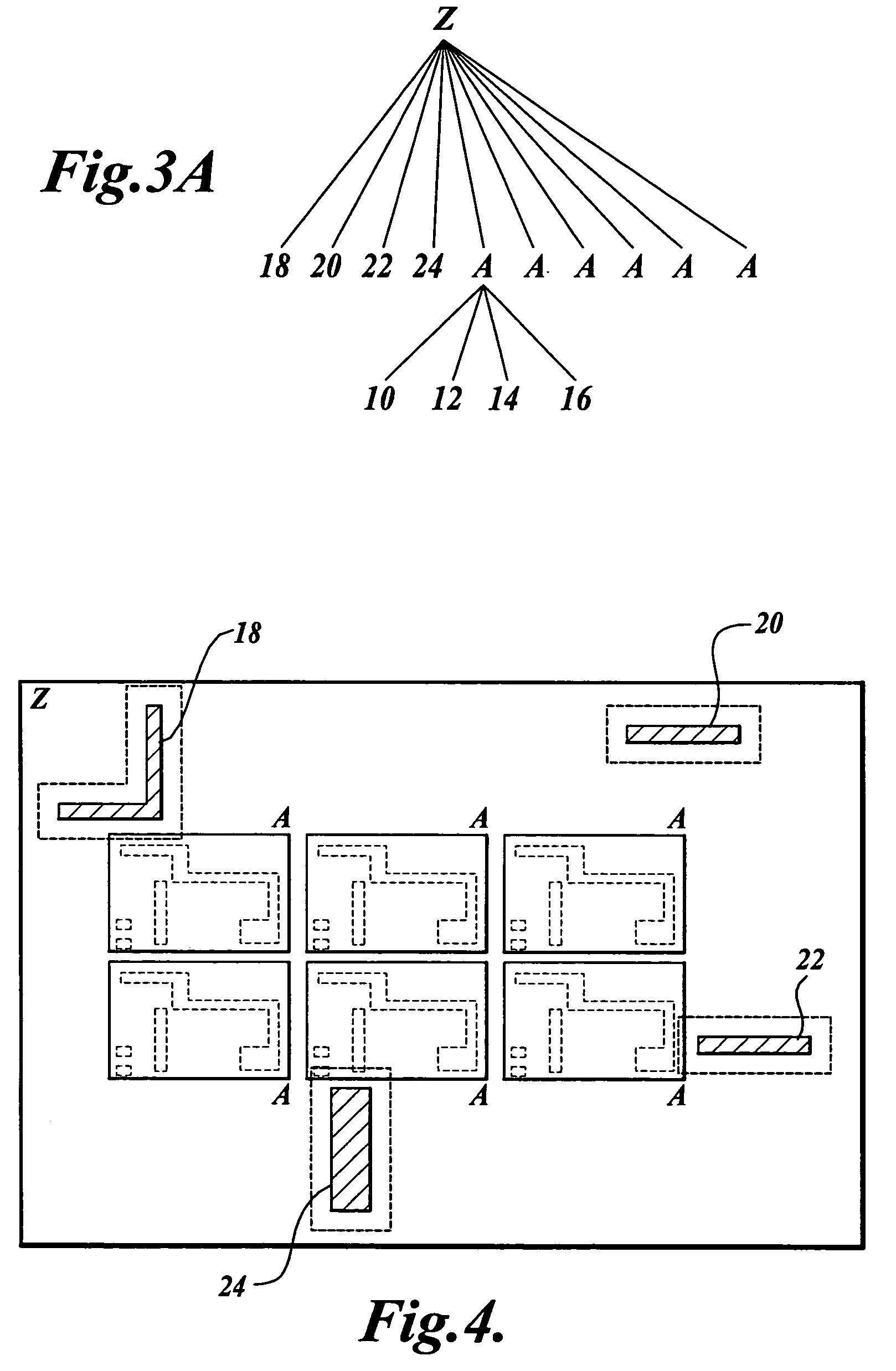
[0029]FIG. 1 illustrates a hypothetical portion of a level in a hierarchical database. The database level referred to as level “A”, includes a number of polygons 10, 12, 14, 16 that define regions to be exposed (or not exposed) on a semiconductor wafer or other object. Typically, such regions represent circuit elements such as transistors, gates, areas to be doped, interconnect wires, contact pads, etc. The particular polygons shown are for purposes of illustration and are not meant to represent actual circuit elements. As indicated above, in the most common formats, e.g., GDSII, each polygon in the database is described by a number of vertices such as those shown in...


PUM

PropertyMeasurementUnit
physicalaaaaaaaaaa
sizeaaaaaaaaaa
densityaaaaaaaaaa

Abstract

A tool for optimizing the layout of a microdevice adds fragmentation points to polygons in a first hierarchical database layer in a manner suitable for application of a tool to apply a resolution enhancement technique (RET) such as optical and process correction (OPC). Portions of polygons in a database level that interact with polygons of a second level in the database are promoted to the second database level, and refragmented. The RET operates on the polygons of the first and second levels of the database to determine how polygons of each of the first and second levels should be adjusted, if necessary, such that the layout is optimized.

Description

CROSS-REFERENCE TO RELATED APPLICATION[0001]This application is a continuation of prior application Ser. No. 10 / 057,309, filed Jan. 24, 2002 now U.S. Pat No. 6,668,367, priority from the filing date of which is hereby claimed under 35 U.S.C. § 120.FIELD OF THE INVENTION[0002]The present invention relates to systems and methods for management of pattern data for creating microdevices and specifically for data manipulation techniques that prepare microdevice layout data for the application of photolithographic resolution enhancement techniques.BACKGROUND OF THE INVENTION[0003]In the field of semiconductor manufacturing, physical descriptions of microdevice layouts are generally represented using data formats such as GDSII. In this representation, individual circuit elements are represented by polygons, which are described as a sequence of vertices. For example, FIG. 1 shows a number of polygons 10, 12, 14, 16 while FIG. 2 shows the same polygons represented as a series of vertices. Th...

Claims


Application Information

Patent Timeline
Patent Type & Authority Patents(United States)
IPC IPC(8): G06F17/50G03F1/00G03F1/36
CPCG03F1/144G03F1/36
Inventor COBB, NICOLAS B.GRODD, LAURENCE W.LIPPINCOTT, GEORGE P.SAHOURIA, EMILE
Owner SIEMENS PROD LIFECYCLE MANAGEMENT SOFTWARE INC
Why Eureka
Try Eureka