
Test apparatus for direct measurement of expansion and shrinkage of oil well cements

a test apparatus and oil well cement technology, applied in the field of laboratory test methods, can solve the problems of inaccurate pressurization and shrinkage measurement, introduction of errors in the shrinkage measurement of test samples, etc., and achieve the effect of convenient reus

Inactive Publication Date: 2007-07-10
SAUDI ARABIAN OIL CO
View PDF24 Cites 42 Cited by
  • Summary
  • Abstract
  • Description
  • Claims
  • Application Information

AI Technical Summary

Benefits of technology

[0013]The vessel assembly receives and isolates the test sample, an incompressible pressurized medium and a second pressurizing medium in three separate volumes in a pressure vessel assembly housing. The test sample is sealed in a sample containing portion at one end of the test vessel using a flexible barrier seal that is placed in contact with the exposed surface of the sample. The incompressible pressurized medium is placed between the flexible seal and a piston. The piston isolates the second pressurizing medium in the end of the test vessel housing opposite the sample containing portion. In the preferred embodiment, pressure is applied to the second medium, and transmitted by the piston to produce an equivalent pressure in the incompressible medium, which is applied through the flexible seal to the test sample. The piston is thereby pressure balanced between the pressurized medium and the pressurizing medium and moves in response to volume changes in the test sample.

Problems solved by technology

Cement testing apparatus that use pistons to directly pressurize and measure the changes in test samples can introduce errors into measuring test sample shrinkage.
These errors occur when portions of the cement test sample build up between the edges of the piston and vessel assembly wall and prevent or slow the downward movement of the piston.
This can result in an inaccurate pressurization and measurement of the shrinkage by the pressurizing piston during the test.

Method used


Image

  • Test apparatus for direct measurement of expansion and shrinkage of oil well cements
  • Test apparatus for direct measurement of expansion and shrinkage of oil well cements
  • Test apparatus for direct measurement of expansion and shrinkage of oil well cements

Examples


Embodiment Construction

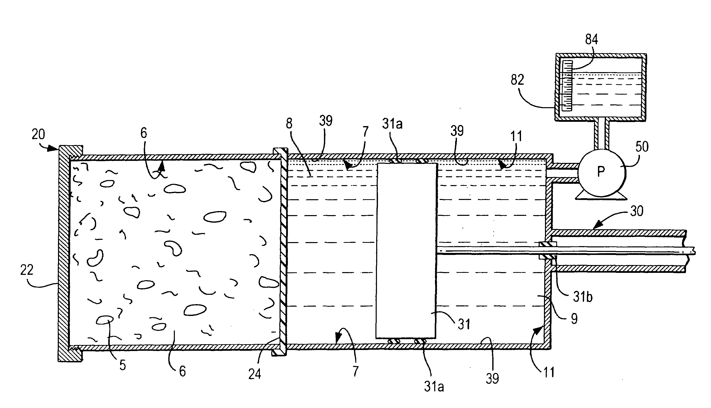
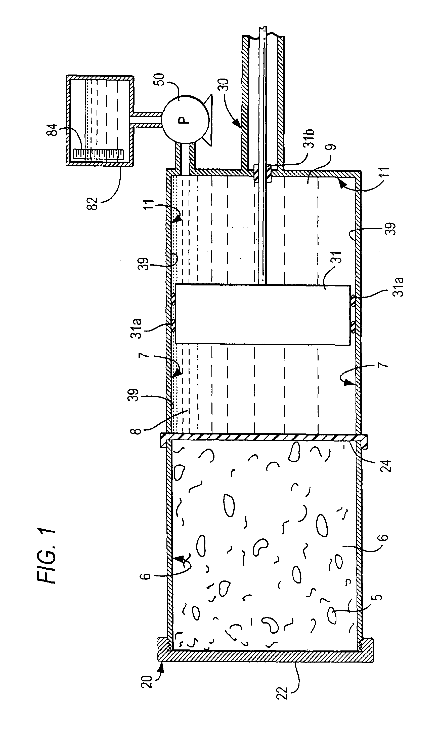
[0040]With reference to FIG. 1, a simplified schematic view of a pressure vessel assembly housing 20 is shown with a fresh sample 5 filling a sample containing portion 6 with its inner surface covered securely by a flexible barrier seal 24 and the housing 20 closed by threaded end cap 22. A first pressurized chamber 7 contains pressurized liquid 8, which is preferably water. All entrained air has been removed from the sample 5 and air has been excluded from the liquid in the first chamber 7. A piston 31 with seals 31a, which can be O-rings, is movably positioned in a bore section 39 of housing 20. A second pressurizing chamber 11 is formed in the end of housing 20 and contains a pressurizing fluid 9 that is in fluid communication with external reservoir 82. A pump 50 is activated to maintain the desired pressure on the preferably incompressible pressurizing fluid in second chamber 11.

[0041]With continuing reference to FIG. 1, a sensor assembly 30, includes a direct mechanical connec...


PUM

PropertyMeasurementUnit
pressureaaaaaaaaaa
volumeaaaaaaaaaa
thicknessaaaaaaaaaa

Abstract

A test apparatus for the measurement of expansion and / or shrinkage of a cement test sample during curing under pressure and temperature conditions that simulate downhole oil well conditions isolates the test sample from a first fixed volume of incompressible pressurized liquid using a flexible barrier that forms a wall of a first chamber in a pressure vessel assembly. The first chamber is sealed by a movable piston. A second pressurizing medium is contained in a second chamber on the opposite side of the piston, and is in fluid communication with a pump, whereby the piston is pressure-balanced between the first and the second medium. The piston moves in a bore of the vessel assembly in response to changes in the volume of the test sample during curing and the amount of linear movement of the piston is detected by a sensor system that measures, correlates and transmits any change in the position of the piston as a change in the sample volume for display and recording.

Description

FIELD OF THE INVENTION[0001]The invention relates to a laboratory test method of and an apparatus for determining shrinkage and expansion in cement test samples and specifically to a laboratory test method of and apparatus for measuring volume changes in cement compositions that are subject to high temperatures and pressures.BACKGROUND OF THE INVENTION[0002]During oil and gas well drilling operations, it is often necessary to seal the space between the outer casing string, or pipe and the rock formation through which the drill has passed in order to prevent the undesired flow of fluids including gas, oil and incompressible media such as water. Undesirable fluid flow can be in an upward direction either along the well pipe casing or downwardly where it might be dissipated into the formations below and / or mixed with other fluids.[0003]A variety of compositions are pumped into the bore hole adjacent to the rock formation for the purpose of providing a tight seal between the metal well ...

Claims


Application Information

Patent Timeline
Patent Type & Authority Patents(United States)
IPC IPC(8): G01F17/00G01N19/00G01N33/38G01F22/00G01F22/02G01N3/02G01N3/12
CPCG01F22/00G01F22/02G01N3/12G01N33/383G01N2203/0226G01N2203/0232G01N2203/0246G01N2203/0256G01N2203/0284
Inventor JENNINGS, SCOTT STEVEN
Owner SAUDI ARABIAN OIL CO
Learn More