Chip card

a chip card and contactless technology, applied in the field of contactless chip cards and contactless chip cards, can solve the problems of high cost, complex production process of chip cards by laminating process, and the possibility at any time of antenna coil windings from the substrate, and achieve the effect of simple and low cos

Inactive Publication Date: 2007-07-10
CIRCLE SMART CARD +1
View PDF22 Cites 37 Cited by
  • Summary
  • Abstract
  • Description
  • Claims
  • Application Information

AI Technical Summary

Benefits of technology

[0010]An object of the invention is therefore to provide a contactless chip card and develop a method for producing a chip card in such a way that the chip card can be produced in a simple and low-cost manner and that damage to the antenna coil integrated in the chip card produced is ruled out.
[0014]In an advantageous development, the device is arranged on the plastic carrier in such a way that, when the plastic carrier is introduced into the injection mold, the device is arranged on a side of the injection mold that is opposite from the side having an injection runner. This has the advantage that the device arranged on the carrier is not damaged by the pressure produced during the injection of the molding compound.
[0015]The contactless chip card according to the invention, comprising a card body and a plastic carrier arranged in the card body, a coil arranged on the plastic carrier and a device having an integrated circuit which is connected in an electrically conducting manner to the coil, is formed in such a way that the coil is arranged on an upper side of the plastic carrier that is opposite from the device. The positioning of the coil on the upper side of the plastic carrier has the advantage that the chip card can be produced in a low-cost injection-molding processes.

Problems solved by technology

The production of a chip card by means of a laminating process is very elaborate and cost-intensive.
The pressure resulting from the injection of the molding compound into the mold means that there is the possibility at any time of the windings of the antenna coil becoming detached from the substrate.

Method used


Image

  • Chip card
  • Chip card

Examples


Embodiment Construction

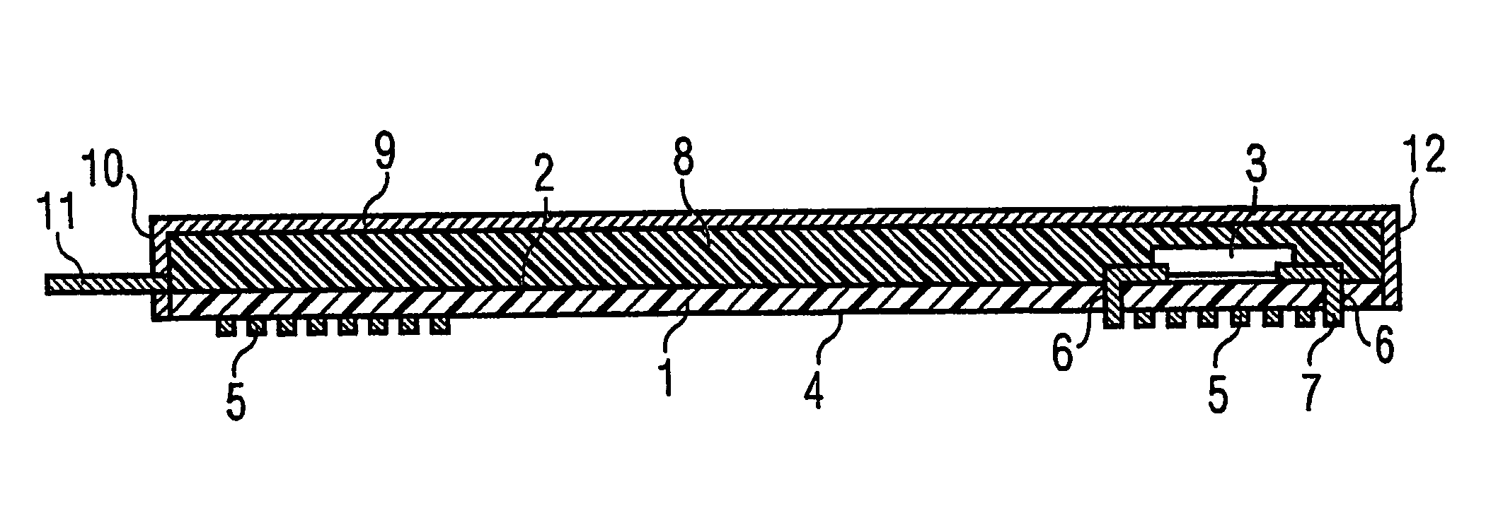
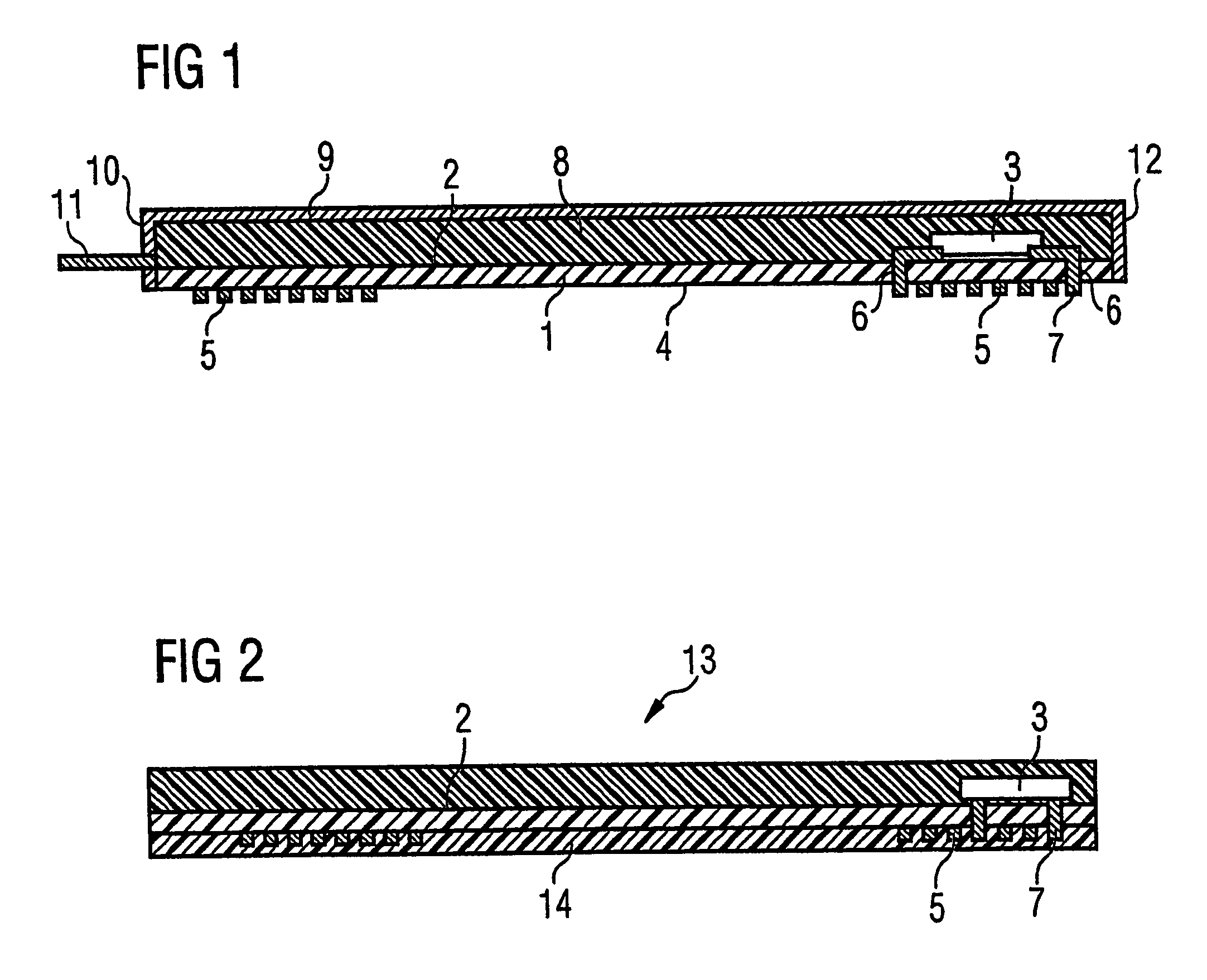
[0020]FIG. 1 is intended to explain the method according to an embodiment og the invention for producing a chip card. A plastic carrier 1, on which a semiconductor chip 3 with contact areas that are not represented here is arranged on a rear side 2, is used in a method according to the invention. Applied to the upper side 4 of the plastic carrier 1 that is opposite from the semiconductor chip 3 is an antenna coil 5. The antenna coil 5 is connected in an electrically conducting manner to the semiconductor chip 3 by means of via holes 7 through clearances 6 arranged in the plastic carrier 1.

[0021]To produce a card body 8, the plastic carrier 1 is introduced into an injection mold 9, the cavity of which is formed in a way corresponding to the shape of the card body 8 to be formed. In this case, the plastic carrier 1 is aligned in the injection mold 9 in such a way that the cavity of the injection mold 9 encloses only the rear side 2 of the carrier 1. The injection mold 9 has on one sid...


PUM

PropertyMeasurementUnit
electrically conductingaaaaaaaaaa
metallicaaaaaaaaaa
electrically conductiveaaaaaaaaaa

Abstract

A contactless chip card and a method for producing a contactless chip card in which a plastic carrier having clearances is provided, on which an antenna coil is arranged on an upper side of the plastic carrier and a device having an integrated circuit is arranged on a rear side of the plastic carrier that is opposite from the upper side, an electrical connection is produced between the coil and the device, the plastic carrier is introduced into an injection mold and a card body is molded onto the rear side of the plastic carrier by the injection-molding process.

Description

CROSS-REFERENCE TO RELATED APPLICATION[0001]This application claims priority to German Patent Application Ser. No. 102004011702.0, filed Mar. 10, 2004, and which is incorporated herein by reference in its entirety.FIELD OF THE INVENTION[0002]The present invention relates to a method for producing a contactless chip card and to a contactless chip card.BACKGROUND OF THE INVENTION[0003]Production of contactless chip cards of a standardized format takes place for example by the laminating process, in which an antenna coil and at least one semiconductor chip are arranged on a carrier film and integrated in a card body formed by laminating a number of films.[0004]A further procedure envisages the arrangement of the semiconductor chip and an antenna coil on a substrate to which the card body is applied by a molding process, so that the card body completely covers the semiconductor chip and the antenna coil.[0005]In DE 197 32 353 A1 there is specified a method for producing a contactless ch...

Claims


Application Information

Patent Timeline
Patent Type & Authority Patents(United States)
IPC IPC(8): G06K19/06B42D15/10B29C45/14G06K19/07G06K19/077H01L21/52
CPCB29C45/14647B29C45/14836G06K19/07724G06K19/0773G06K19/07749B29C2045/14844B29L2031/3456
Inventor PUSCHNER, FRANKPROSKE, REINHARDSTAMPKA, PETERMULLER-HIPPER, ANDREAS
Owner CIRCLE SMART CARD
Why Eureka
Try Eureka