Universal connector assembly and method of manufacturing

a technology of universal connectors and assembly methods, applied in the field of electronic components, can solve the problems of not optimizing the foregoing configurations in terms of application flexibility, each of the foregoing solutions is limited, and the situation is less than optimal, and achieves the effect of flexible application and configuration

Active Publication Date: 2007-07-10
PULSE ELECTRONICS
View PDF33 Cites 131 Cited by
  • Summary
  • Abstract
  • Description
  • Claims
  • Application Information

AI Technical Summary

Problems solved by technology

However, the foregoing prior art configurations are not optimized in terms of application flexibility, as well as their other required attributes.
Specifically, each of the foregoing solutions is limited to one particular configuration selected at the time of manufacture.
This situation is less than optimal, since it requires at least some separation of manufacturing process, distribution, stocking, and sale (e.g., different manufacturing lines, labeling, cataloging, part numbers, etc.).

Method used


Image

  • Universal connector assembly and method of manufacturing
  • Universal connector assembly and method of manufacturing
  • Universal connector assembly and method of manufacturing

Examples


embodiment

Multi-Port Embodiment

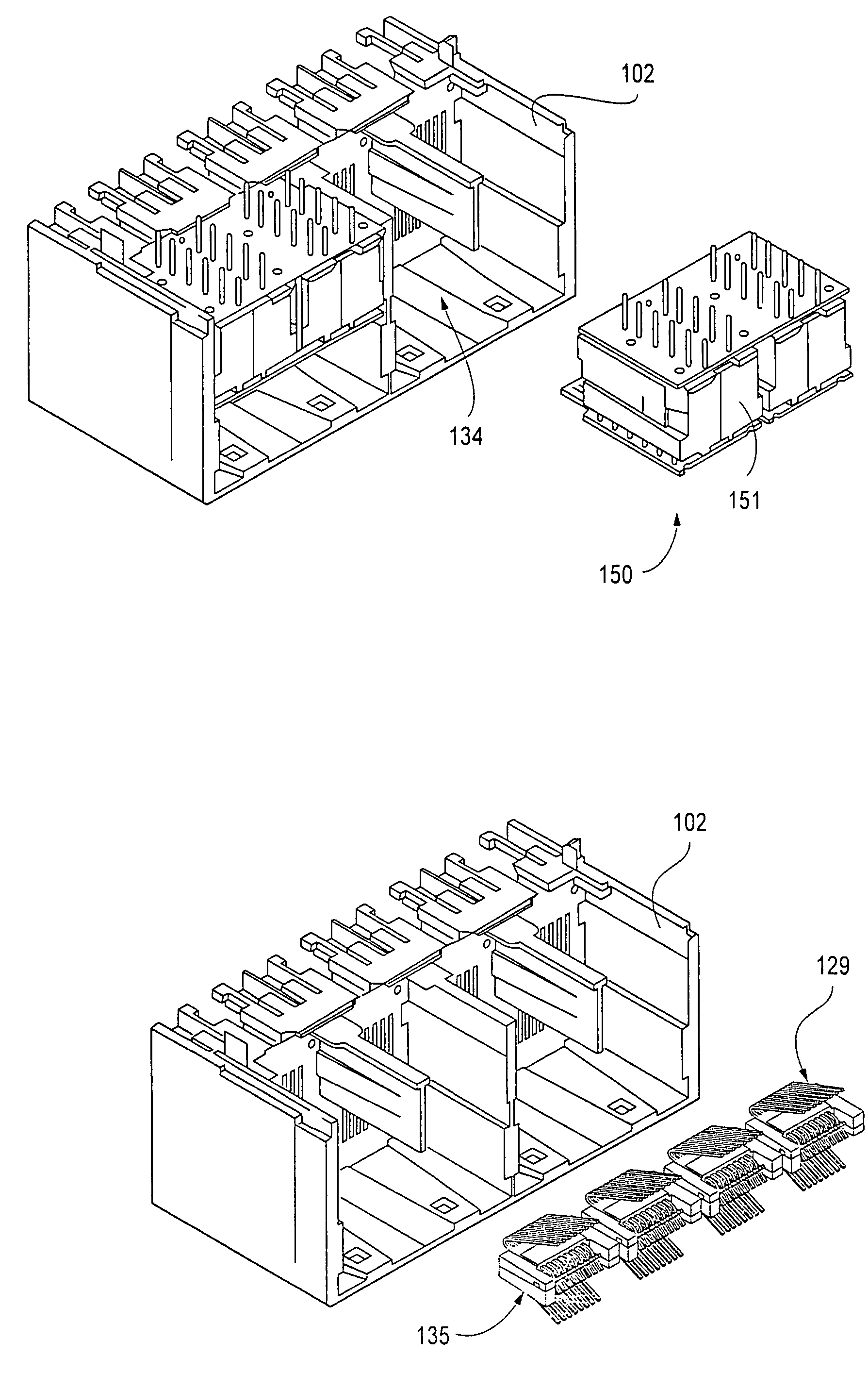
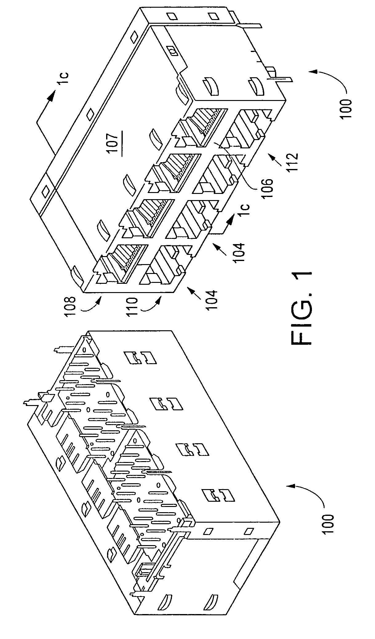
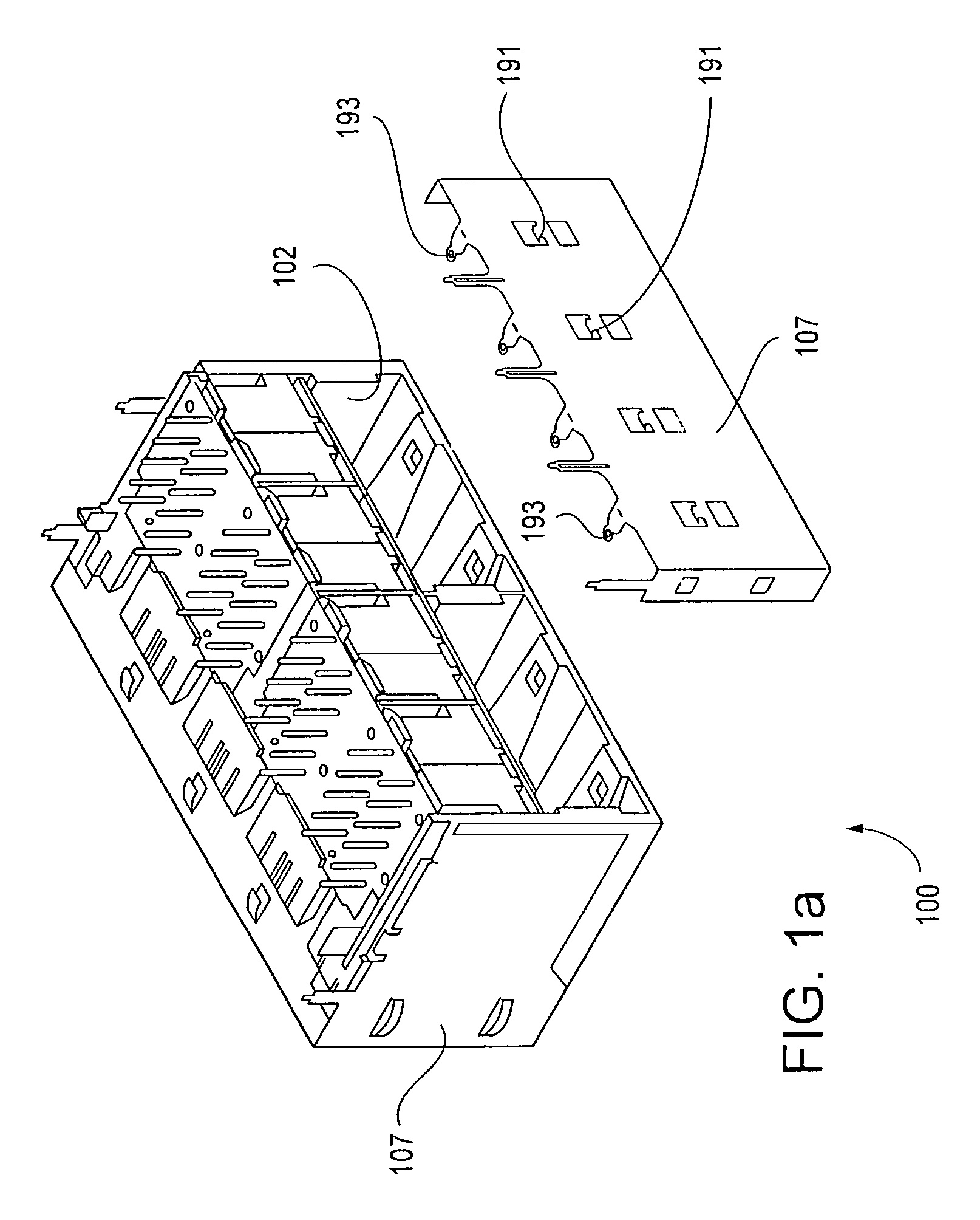
[0060]Referring now to FIGS. 1–1o, a first embodiment of the connector assembly of the present invention is described. As shown in FIG. 1, the assembly 100 generally comprises a connector housing element 102 having a plurality of individual connectors 104 formed therein. Specifically, the connectors 104 are arranged in the illustrated embodiment in side-by-side row fashion within the housing 102 such that two rows 108, 110 of connectors 104 are formed, one disposed atop the other (“row-and-column”). The front walls 106a of each individual connector 104 are further disposed parallel to one another and generally coplanar, such that modular plugs may be inserted into the plug recesses 112 formed in each connector 104 simultaneously without physical interference. The plug recesses 112 are each adapted to receive one modular plug (not shown) having a plurality of electrical conductors disposed therein in a predetermined array, the array being so adapted to mate with ...


PUM

PropertyMeasurementUnit
electricallyaaaaaaaaaa
electrically conductiveaaaaaaaaaa
electricalaaaaaaaaaa

Abstract

An advanced modular plug connector assembly incorporating an insert assembly disposed in the rear portion of the connector housing. In one embodiment, the connector has a plurality of ports in multi-row configuration, and the insert assembly includes a substrate adapted to receive one or more electronic components such as choke coils, transformers, or other signal conditioning elements or magnetics. The substrate also interfaces with the conductors of two modular ports of the connector, and is removable from the housing such that an insert assembly of a different electronics or terminal configuration can be substituted therefor. In this fashion, the connector can be configured to a plurality of different standards (e.g., Gigabit Ethernet and 10 / 100). In yet another embodiment, the connector assembly comprises a plurality of light sources (e.g., LEDs) received within the housing. Methods for manufacturing the aforementioned embodiments are also disclosed.

Description

PRIORITY[0001]This application claims priority to U.S. Provisional Patent Application Ser. No. 60 / 583,989 filed Jun. 29, 2004 of the same title, which is incorporated herein by reference in its entirety.COPYRIGHT[0002]A portion of the disclosure of this patent document contains material that is subject to copyright protection. The copyright owner has no objection to the facsimile reproduction by anyone of the patent document or the patent disclosure, as it appears in the Patent and Trademark Office patent files or records, but otherwise reserves all copyright rights whatsoever.[0003]1. Field of the Invention[0004]The present invention relates generally to electronic components, and particularly to an improved design for, and method of manufacturing a single- or multi-connector assembly which may include internal electronic components.[0005]2. Description of Related Technology[0006]Modular connectors, such as for example those of the “RJ” configuration, are well known in the electron...

Claims


Application Information

Patent Timeline
Patent Type & Authority Patents(United States)
IPC IPC(8): H01R24/00
CPCH01R13/514H01R13/719H01R13/518H01R13/6658H01R29/00H01R24/64Y10T29/49002H01R13/6633Y10T29/49208
Inventor MACHADO, RUSSELL LEERENTERIA, VICTOR H.DINH, THUYEN
Owner PULSE ELECTRONICS
Why Eureka
Try Eureka