Metal hydride canister apparatus

a technology of metal hydride and canister, which is applied in the direction of indirect heat exchangers, lighting and heating apparatus, and separation processes, etc., can solve the problems of insufficient ability to filter out impurities and other gases, greater storage challenges, and slow hydrogen flow ra

Active Publication Date: 2007-07-10
IND TECH RES INST
View PDF2 Cites 18 Cited by
  • Summary
  • Abstract
  • Description
  • Claims
  • Application Information

AI Technical Summary

Benefits of technology

[0014]The object of the present invention is to provide a metal hydride canister apparatus having structures capable of discharging hydrogen gas uniformly and exchanging heat effectively, and the apparatus also can effectively filter out impurities and prevent the finer powder of the degraded metal hydride from leaking.
[0015]Another object of the present invention is to provide a metal hydride canister apparatus having structures capable of discharging hydrogen gas uniformly and exchanging heat effectively, such that not only the apparatus is able to maintain a constant flow rate within a specific period of time, but also may enable a larger hydrogen discharging flow rate.
[0016]Yet, another object of the present invention is to provide a metal hydride canister apparatus having structures capable of discharging hydrogen gas uniformly and exchanging heat effectively, such that the apparatus can heat the metal hydride uniformly or absorb the heat released by the metal hydride uniformly for enhancing hydrogen absorbing and discharging capability of the metal hydride.

Problems solved by technology

This poses greater challenges with respect to storage compared to storage of gasoline which is a liquid.
1. When hydrogen quickly enters into and exhausts from the conventional metal hydride tank apparatus, the flow rate of the hydrogen will be quickly slowed down, because of the heat absorption and the heat release of the metal hydride.
2. If the thickness of the filter is not thick enough, then the ability for filtering out the impurities and other gases will be insufficient.
3. If the thickness of the filter is too thick, then the resistance for discharging the hydrogen will be increased.
4. Because the contact area between the single spiral pipe of the heat exchanger and the metal hydride is not large enough, it is impossible to heat the metal hydride uniformly or absorb the heat released by the metal hydride uniformly, such that the hydrogen absorbing and discharging capability of the metal hydride is affected.

Method used


Image

  • Metal hydride canister apparatus
  • Metal hydride canister apparatus
  • Metal hydride canister apparatus

Examples


Embodiment Construction

[0029]For your esteemed members of reviewing committee to further understand and recognize the fulfilled functions and structural characteristics of the invention, a preferable embodiment cooperating with detailed description is presented as the follows.

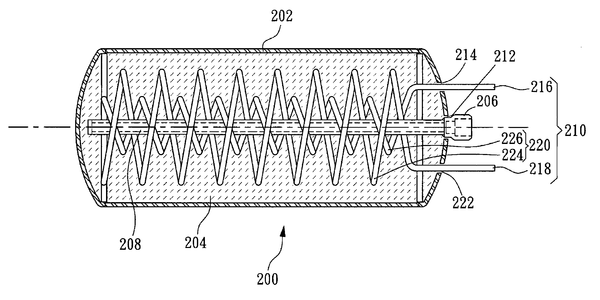
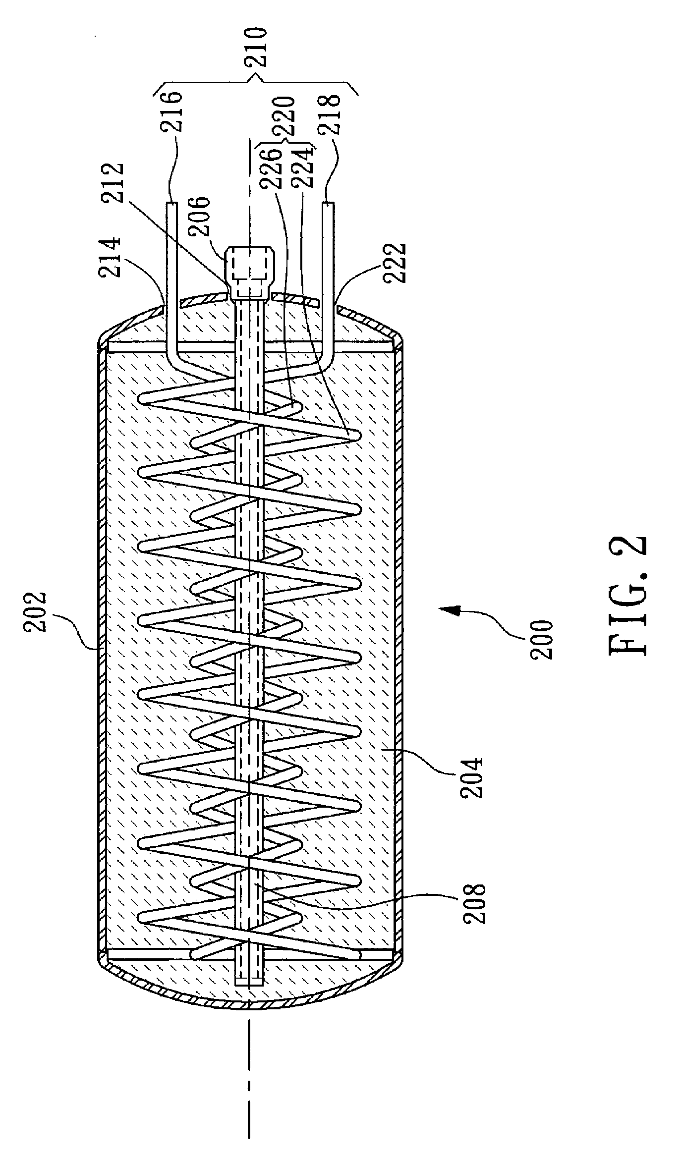
[0030]Please refer to FIG. 2, which is a cross-sectional view illustrating a preferred embodiment of a metal hydride canister apparatus having structures capable of discharging hydrogen gas uniformly and exchanging heat effectively according to the present invention. As seen in FIG. 2, the metal hydride canister apparatus 200 is adapted for connecting to a hydrogen-filling apparatus (not shown) or a fuel cell (not shown). In the present embodiment, the apparatus 200 mainly comprises: a shell 202, a filtering rod 208, and a guiding pipe 210. Wherein, the top of the shell 202 has a central hole 212 and a connector 206, which is arranged in the central hole 212, and the connector 206 and the shell 202 may be connected by means of weldin...


PUM

PropertyMeasurementUnit
inner diametersaaaaaaaaaa
diameteraaaaaaaaaa
electrical energyaaaaaaaaaa

Abstract

The present invention provides a metal hydride canister apparatus having structures capable of discharging hydrogen gas uniformly and exchanging heat effectively, comprising: a shell having a joint arranged in a central hole located on top of the shell, and two via holes arranged respectively at a side of the central hole; a filtering rod connecting to the joint; a pipe having a first end, a second end and a middle section between the first end and the second end; and a metal hydride stored inside the shell; wherein, the first end and the second end of the pipe pass the corresponding via hole in respective, and the middle section of the pipe forms a twin spiral structure wrapping around the filtering rod, the middle section having a first loop interconnecting to a second loop. In a preferred embodiment of the present invention, the filtering rod can be a hollow rod extending toward the bottom of the shell, and is welded on the joint that is further welded to the central hole, in addition, the first end and the second end of the pipe are welded onto the corresponding via holes and are exposed to the outside of the shell, and the first loop and the second loop of the middle section can have equal diameters or different diameters.

Description

FIELD OF THE INVENTION[0001]The invention is related to a metal hydride canister apparatus, and more particularly, to a metal hydride canister apparatus having structures capable of discharging hydrogen gas uniformly and exchanging heat effectively.BACKGROUND OF THE INVENTION[0002]A fuel cell provides electricity and heat at the same time by electrochemically reacting a fuel gas such as hydrogen with an oxidant gas such as air in catalytic layers of electrodes. Fuel cells offer the possibility of converting chemically bonded energy directly into electrical energy which can be subsequently converted into mechanical drive energy with the aid of an electric motor. Present day preferred fuel cells consume hydrogen and oxygen and convert these elements into the environmentally friendly end product, namely, water.[0003]Hydrogen is the most direct fuel of fuel cell, that is, it can be used without the conversion of reformer. Hydrogen is a substance with high energy content compared to its ...

Claims


Application Information

Patent Timeline
Patent Type & Authority Patents(United States)
IPC IPC(8): B01D53/02C01B3/00F17C3/00F17C11/00H01M8/04
CPCC01B3/0005F17C11/005Y02E60/321Y02E60/324Y02E60/32
Inventor WU, CHOU-ZONGHSU, CHI-TANG
Owner IND TECH RES INST
Why Eureka
Try Eureka