Unlock instant, AI-driven research and patent intelligence for your innovation.

System and method for communicating with an appliance through an optical interface using a control panel indicator

Inactive Publication Date: 2007-07-10
NIDEC MOTOR CORP
View PDF129 Cites 40 Cited by
  • Summary
  • Abstract
  • Description
  • Claims
  • Application Information

AI Technical Summary

Benefits of technology

[0015]In a preferred implementation of the present invention, the physical layer is a universal asynchronous receiver / transmitter (UART) that is coupled to the indicator. The UART, under control of the electronic controller, provides a data signal to the indicator so the indicator is modulated in accordance with the data signal. The use of a UART or equivalent device enables the controller to modulate the indicator without requiring the electronic controller to time each bit of the data signal to the indicator. The UART or equivalent device implementing the physical layer may also receive a data signal from a phototransistor or a LED responding to an optical signal being transmitted by an external device. The signal is processed by the UART and made available to the controller, preferably on a byte by byte or word by word basis.
[0024]The system and method of the present invention provide effective communication management in an appliance without significantly increasing the costs of manufacturing an appliance.

Problems solved by technology

The use of electronic controllers has added to the complexity of servicing appliances.
Small electronic integrated circuits do not lend themselves to the methods of troubleshooting and repair that have historically been used with mechanical and electromechanical devices.
Accordingly, malfunctions in an electronically controlled appliance are more difficult to diagnose and resolve than those of the old, mechanical cam controlled devices.
However, infrared and radio communication modules add appreciable expense to the manufacture of appliances.
Because appliance manufacturers operate with relatively low profit margins, an increase of even one dollar in cost is multiplied by the production output, which may be in the millions of units.
Thus, the additional expense of long range communication modules, such as infrared and radio communication devices, may significantly impact the bottom line of an appliance manufacturer.
While the optical interface may support communication with an electronic controller so data may be exchanged with an appliance, data communication problems also arise in the management of the interface and the communication received through it.
One problem that arises regards the amount of resources to allocate to the management of the communication interface.
Another problem with management of the interface in an appliance is the validity of the data.
While network protocols are available that provide data message verification and that assess whether complete messages have been received, such protocols and programs that implement them are not good candidates for optical interface control in an appliance.
For one, they require a lot of memory resources.
The processing of the identifier and forwarding of messages not addressed to the recipient requires overhead processing and resources that may not be available in an appliance.

Method used


Image

  • System and method for communicating with an appliance through an optical interface using a control panel indicator
  • System and method for communicating with an appliance through an optical interface using a control panel indicator
  • System and method for communicating with an appliance through an optical interface using a control panel indicator

Examples


Embodiment Construction

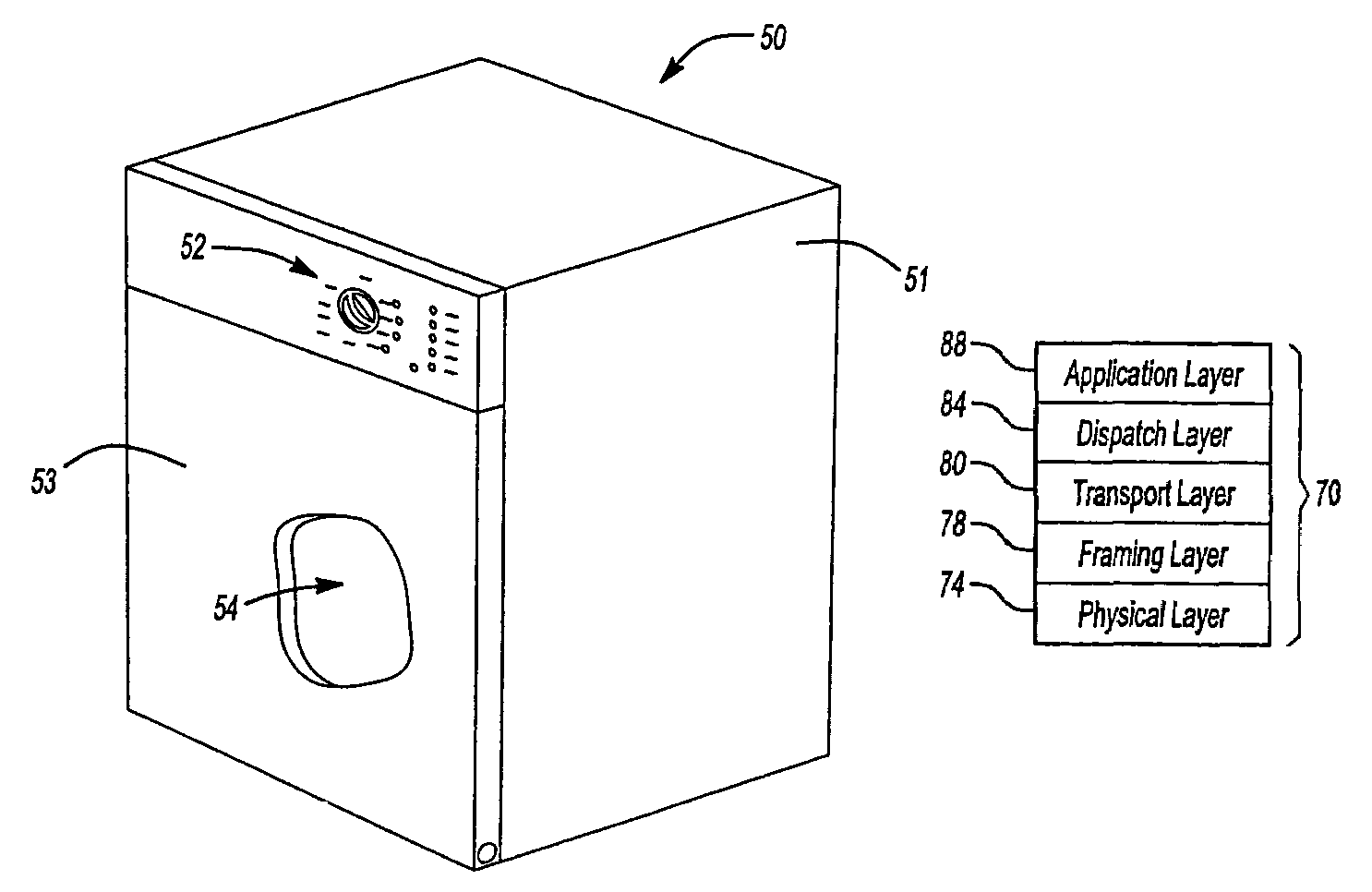
[0039]FIG. 1 shows an exemplary embodiment of a dishwasher 50 in which one or more aspects of the present invention may be incorporated. Dishwasher 50 includes a frame 51, a control panel 52, a door 53, and a tub 54. Door 53 is pivotally attached to frame 51. Door 53 and frame 51 define an enclosure in which is located tub 54. Control panel 52 is affixed to frame 51. The enclosure formed by door 53 and frame 51 also houses control circuits and devices as is known in the art. The exact physical arrangements of door 53, frame 51 and tub 54 are a matter of design choice. For example, control panel 52 may be mounted on door 53 in some embodiments.

[0040]FIG. 2 shows a schematic block diagram of an exemplary appliance circuit 9 that incorporates one or more features of the present invention. Appliance circuit 9 includes a control circuit 10 and a set of electromechanical devices. In the exemplary embodiment described herein, the electromechanical devices include a motor 16a, a heater coil...


PUM


Abstract

The invention is a communication management module for effectively controlling an optical interface that uses a control panel indicator in an appliance for communication. The module includes a physical, framing, transport, dispatch, and application layers. The module is implemented to verify the integrity of data frames and to correlate data frames and responses with applications in the application layer.

Description

FIELD OF THE INVENTION[0001]This invention relates to appliance communication methods and, more particularly, to appliance communication methods that use an optical interface.BACKGROUND OF THE INVENTION[0002]Appliance devices such as dishwashers, clothes washing machines, dryers, ovens, refrigerators and the like often comprised of electromechanical components. Some of these components have knobs or selector switches so a user may control operational parameters of the appliance. In many cases, the overall operation of the appliance is predefined as a general matter and the settings or selections input by a user merely modify the predefined operation in some way.[0003]For example, the operation of a dishwasher typically involves the processes of filling, washing, draining and rinsing. Such operations involve, among other things, the control of water valves, drain valves and motor relays. The general sequence of such operations is generally predefined. However, user input may be used ...

Claims


Application Information

Patent Timeline
IPC IPC(8): G06F13/12G08B5/00G08C19/12A47L15/42D06F34/04D06F34/28H04L1/18H04L29/06H04L29/08
CPCA47L15/4293D06F33/02D06F39/005H04L1/188H04L29/06D06F2216/00H04L69/323H04L69/324H04L69/326H04L69/327D06F34/28D06F2105/58D06F2103/38D06F34/04H04L9/40
Inventor SHEAHAN, THOMAS J.SULLIVAN, MICHAEL P.
Owner NIDEC MOTOR CORP
Features
  • R&D
  • Intellectual Property
  • Life Sciences
  • Materials
  • Tech Scout
  • Unparalleled Data Quality
  • Higher Quality Content
  • 60% Fewer Hallucinations
Learn More