Locking clip

a technology of locking clip and clip, which is applied in the field of clips, can solve the problems of deterioration of canvas, insufficient number of grommets, insufficient strength, and insufficient spacing for providing the necessary support, etc., and achieves the effect of facilitating the installation of the clip

Inactive Publication Date: 2007-07-17
PHOENIX PROD DESIGN GRP
View PDF18 Cites 30 Cited by
  • Summary
  • Abstract
  • Description
  • Claims
  • Application Information

AI Technical Summary

Benefits of technology

[0019]To facilitate installation of the clip to the sheet material and securement of the rope to the clip, an interim locking feature may be incorporated. In the preferred embodiment, the interim locking element may comprise opposed engaging ratchet lips, or pawls/detents, one lip being integrated into the side of the securement hook of the second lever arm and the opposing lip being integrated into the edge formed by the slot and outer face of the first lever arm. As discussed previously, by depressing the lever arms, the teeth on the opposing jaws engage and the lever arms may be elastically deflected relative to each other. When the appropriate clamping pressure has been obtained, the lever arms may be ...

Problems solved by technology

However, with age and weathering, the grommets often fail or the canvas deteriorates and supplemental means are required to secure the existing cover.
However, the grommets are often inadequate in terms of number, spacing, or strength to provide the necessary support.
As a result, the shelters typically fail due to wind loads or rain accumulation.
Often times the tarps have no convenient means for securing them to the vehicle, and, as a result, they noisily flap in the wind and risk being ripped from the vehicle possibly resulting in a dangerous traffic situation.
Although sometimes these coverings have integrated securing mechanisms, failures in the mechanisms or reconfiguration to accommodate unanticipated changes in the load being tra...

Method used


Image

  • Locking clip
  • Locking clip
  • Locking clip

Examples


Embodiment Construction

[0040]a. Overview

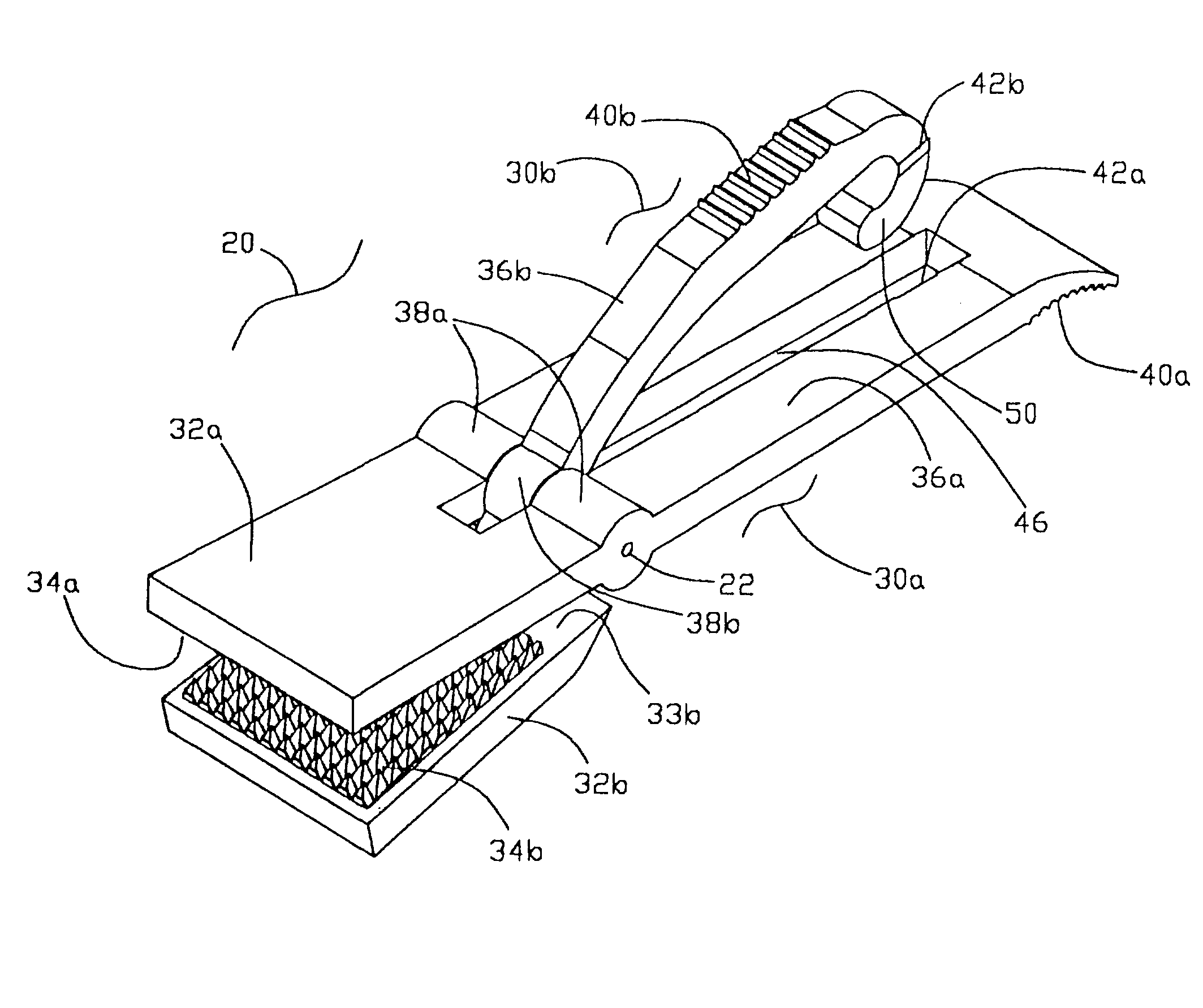
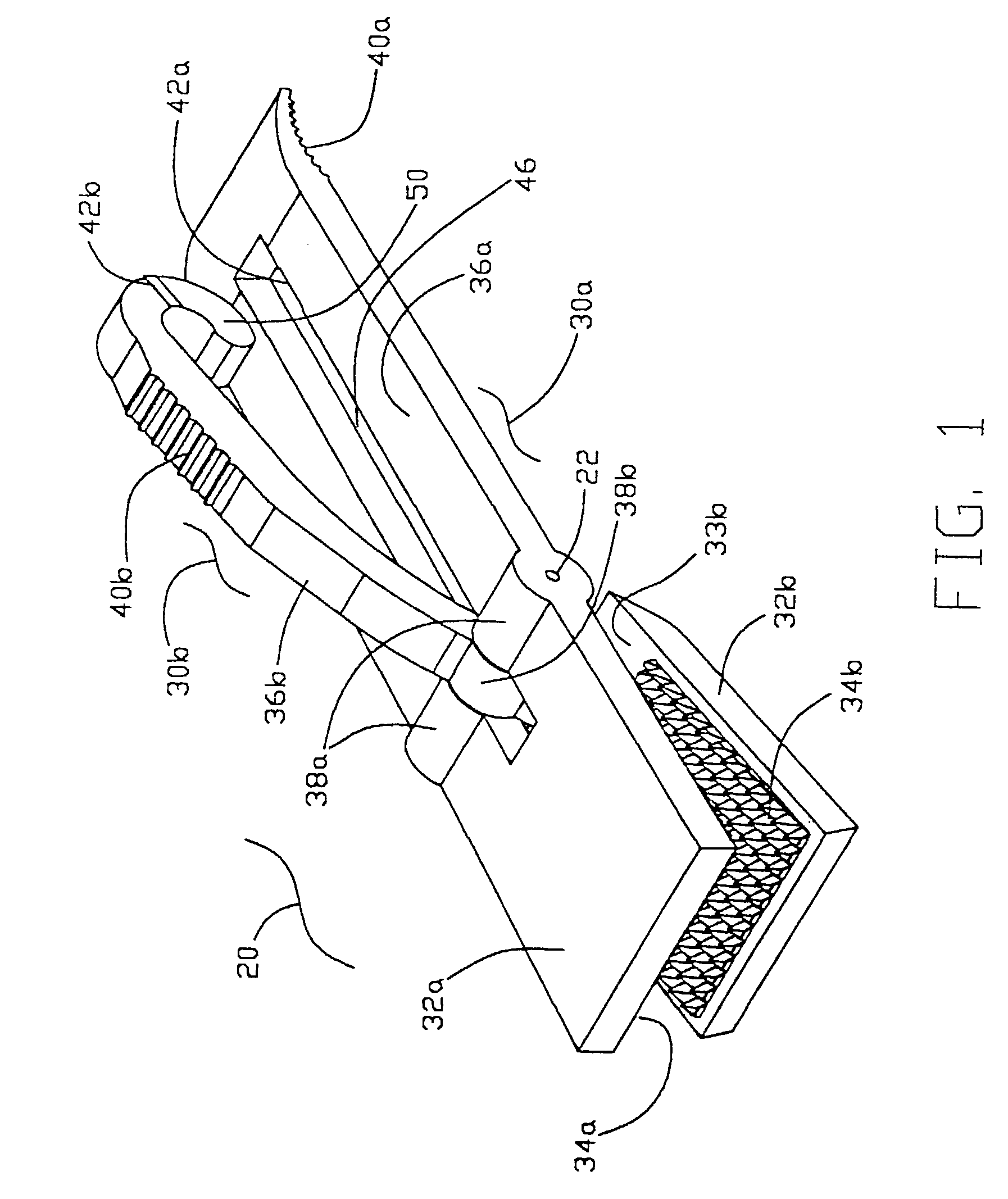
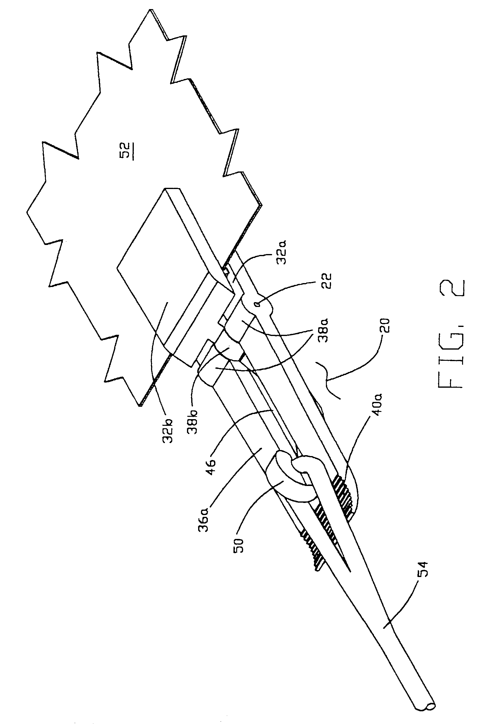
[0041]FIG. 1 shows a clip assembly 20 in accordance with the present invention, and FIG. 2 shows this clip assembly engaging a sheet of material 52 and secured by a rope 54. The preferred embodiment of the clip assembly 20 is formed of two major members, a first gripper arm member 30a (also shown in FIG. 3), and a second gripper arm member 30b (also shown in FIG. 4), which are joined by a hinge pin 22 in opposition to each other to form a pliers like arrangement for gripping a sheet of material 52.

[0042]Each of the first and second gripper arm members 30a, 30b includes several corresponding counterparts including (a) opposing first and second jaw portions 32a, 32b that provide structural support for the corresponding first and second grip elements 34a, 34b which engage the sheet of material 52; (b) first and second lever arm portions 36a, 36b that extend from the first and second jaw portions 32a, 32b to provide leveraged activation of the first and second jaws 32a,...


PUM


Abstract

A clip assembly having first and second pivoting gripping members that are locked in gripping engagement to a tarp or other material and attached to a rope or shock cord. The gripping members include jaws and arms that are joined by a pivot connection so that the jaws are forced into engagement when the arms are pressed together. At least one of the arms is formed of a resiliently flexible material so that the arm bends as the jaws are forced into gripping engagement. There is a hook or other attachment portion on one of the arms that the arms are locked in the compressed position when a portion of the cord is passed therethrough. The hook may include a primary opening for receiving a bight of a rope and a secondary opening for receiving a hook on the end of a shock cord.

Description

[0001]This application claims the priority of U.S. provisinal patent application Ser. No. 60 / 364,208, filed on 13 Mar. 2002.BACKGROUND OF THE INVENTION[0002]a. Field of the Invention[0003]The present invention relates generally to clips and similar gripping devices and, more particularly, to a locking clip that grips sheets of cloth, plastic or other material[0004]b. Background Art[0005]Numerous clips and other gripping devices have been proposed for gripping or cloth, plastic or other sheet-type materials. Some common examples include suspender clips for gripping pants, clothespins for securing clothing to the drying line, and binder clips for binding stacks of paper. Adaptations on clips of this nature have been used as an improvised means of securing canvas tarps or plastic sheets in an attempt to protect articles from environmental conditions, and certain gripping devices have evolved specifically for this type of application.[0006]Tarps and other sheet coverings of course have ...

Claims


Application Information

Patent Timeline
IPC IPC(8): A41F11/00B60P7/08F16B5/06
CPCB60P7/0807F16B5/0692Y10T24/4453Y10T24/44547Y10T24/44658Y10T403/591
Inventor ANDERSEN, TODD DCAMERON, ROBERT M
Owner PHOENIX PROD DESIGN GRP
Why Eureka
Try Eureka