Car wash conveyor

a conveyor and car wash technology, applied in the direction of transportation and packaging, rope railways, train hauling devices, etc., can solve the problems of excessive wear and flat spots on the track, and achieve the effect of excessive wear and flat spots

Active Publication Date: 2007-07-17
PISTON OPW INC
View PDF5 Cites 25 Cited by
  • Summary
  • Abstract
  • Description
  • Claims
  • Application Information

AI Technical Summary

Benefits of technology

[0010]A first inventive aspect of the present disclosure is the design and construction of an improved conveyor dolly which permits the use of a narrow track slot while at the same time provides stability in the engagement of the dolly with an automobile tire. In general, this is accomplished by providing a dolly having an axle member, a center link mounted on the axle member, a first pair of relatively closely spaced larger diameter tire engaging rollers on opposite sides of the center link, a pair of smaller diameter track engaging rollers mounted on the axle member in reversely similar relationship and outboard of the tire engaging rollers and a pair of tire stabilizing rollers mounted on the axle member in reversely similar relationship and outboard of the track engaging rollers. The tire stabilizing rollers are arranged to ride above and out of contact with the tracks but to at least approximately equal the diameter of the tire engaging rollers at a point of tangency with the tire tread. The stabilizing rollers prevent contact between the tread surface of the tire and the track engaging rollers, which contact would otherwise tend to stall the track engaging rollers and cause them to skid along the track, an undesirable situation which produces flat spots and excessive wear on the track engaging rollers. All of the rollers of the present invention lie on or above the top surfaces of the track rails when in operation.

Problems solved by technology

The stabilizing rollers prevent contact between the tread surface of the tire and the track engaging rollers, which contact would otherwise tend to stall the track engaging rollers and cause them to skid along the track, an undesirable situation which produces flat spots and excessive wear on the track engaging rollers.

Method used


Image

  • Car wash conveyor
  • Car wash conveyor
  • Car wash conveyor

Examples


Embodiment Construction

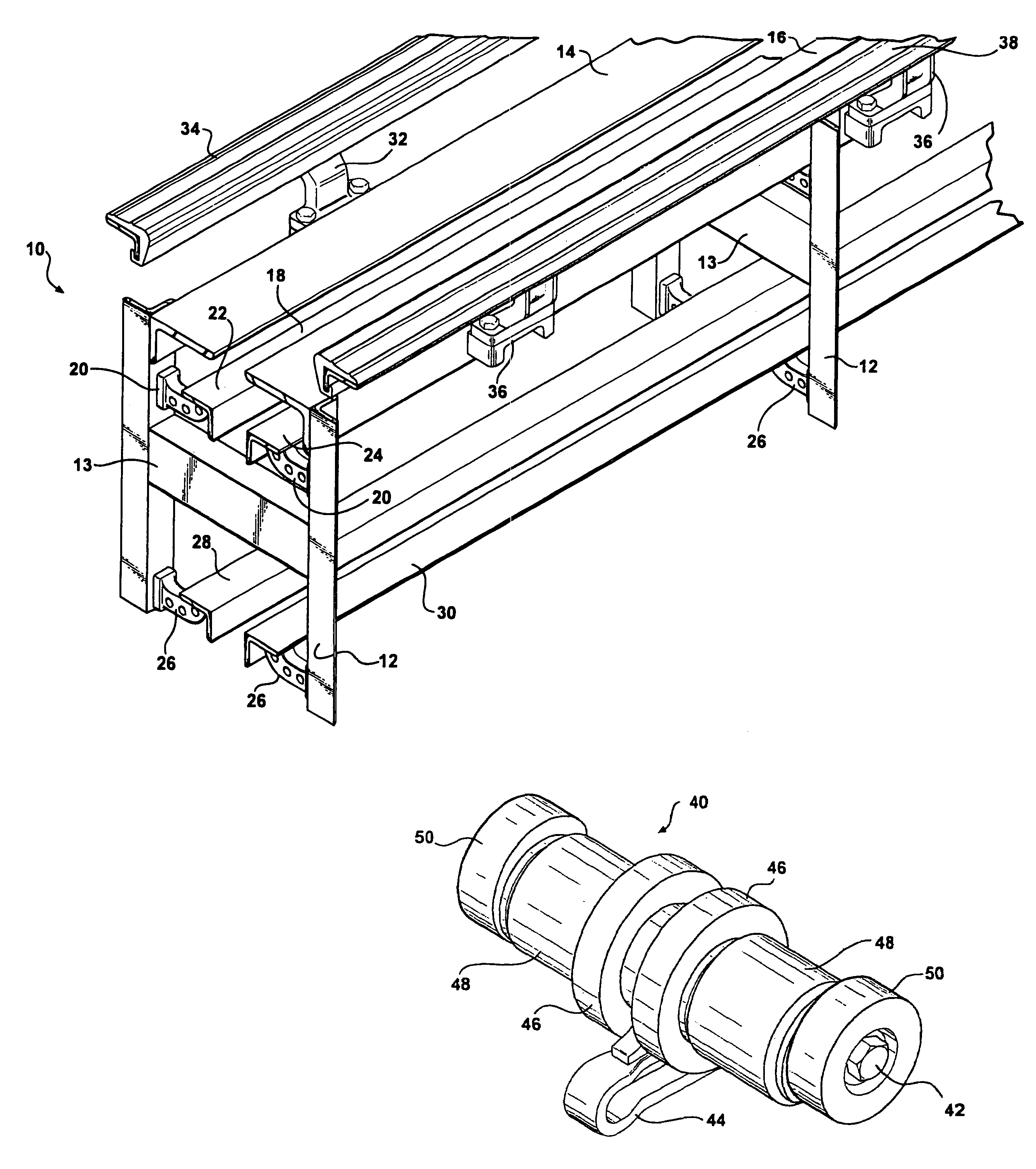
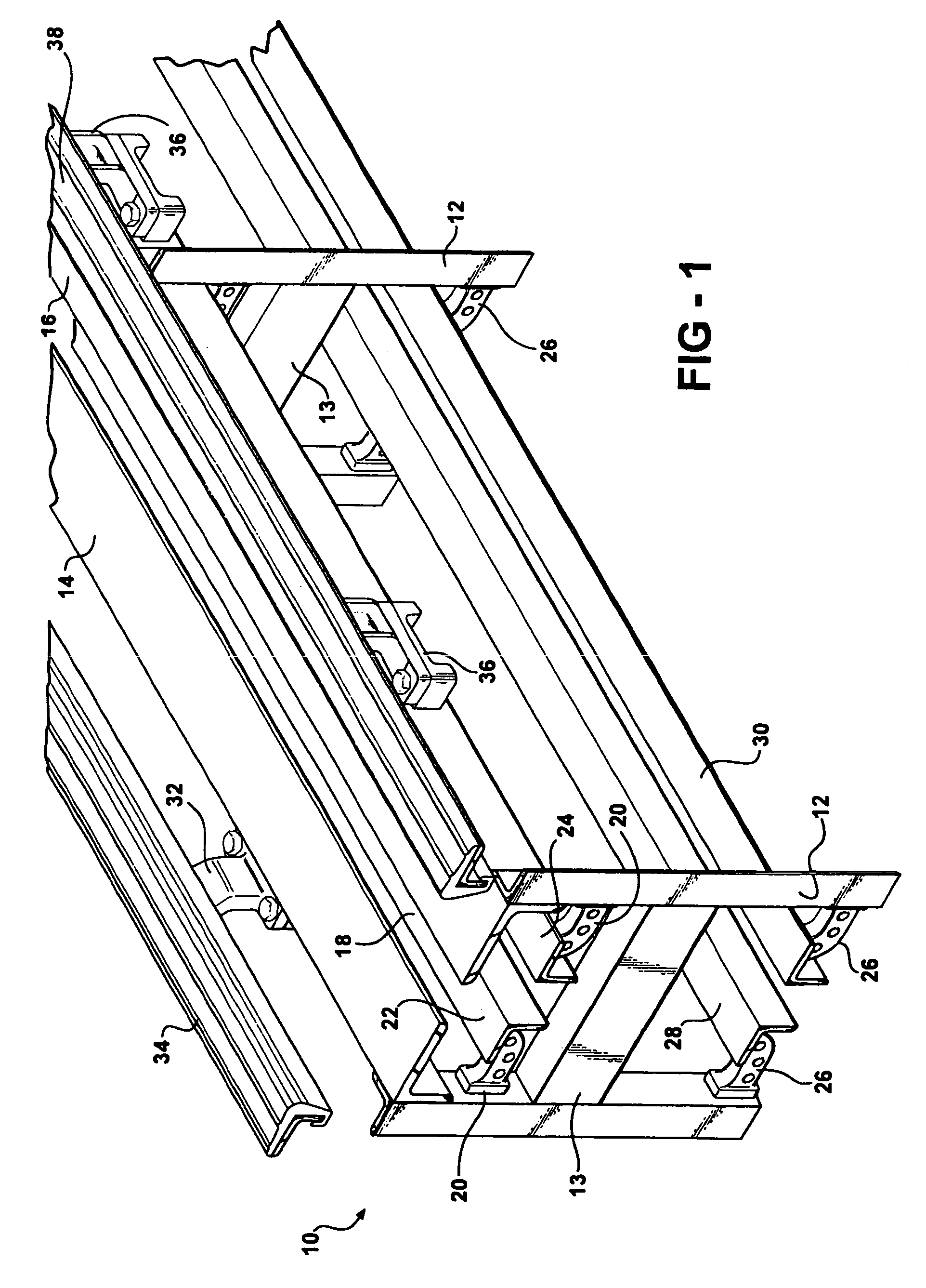
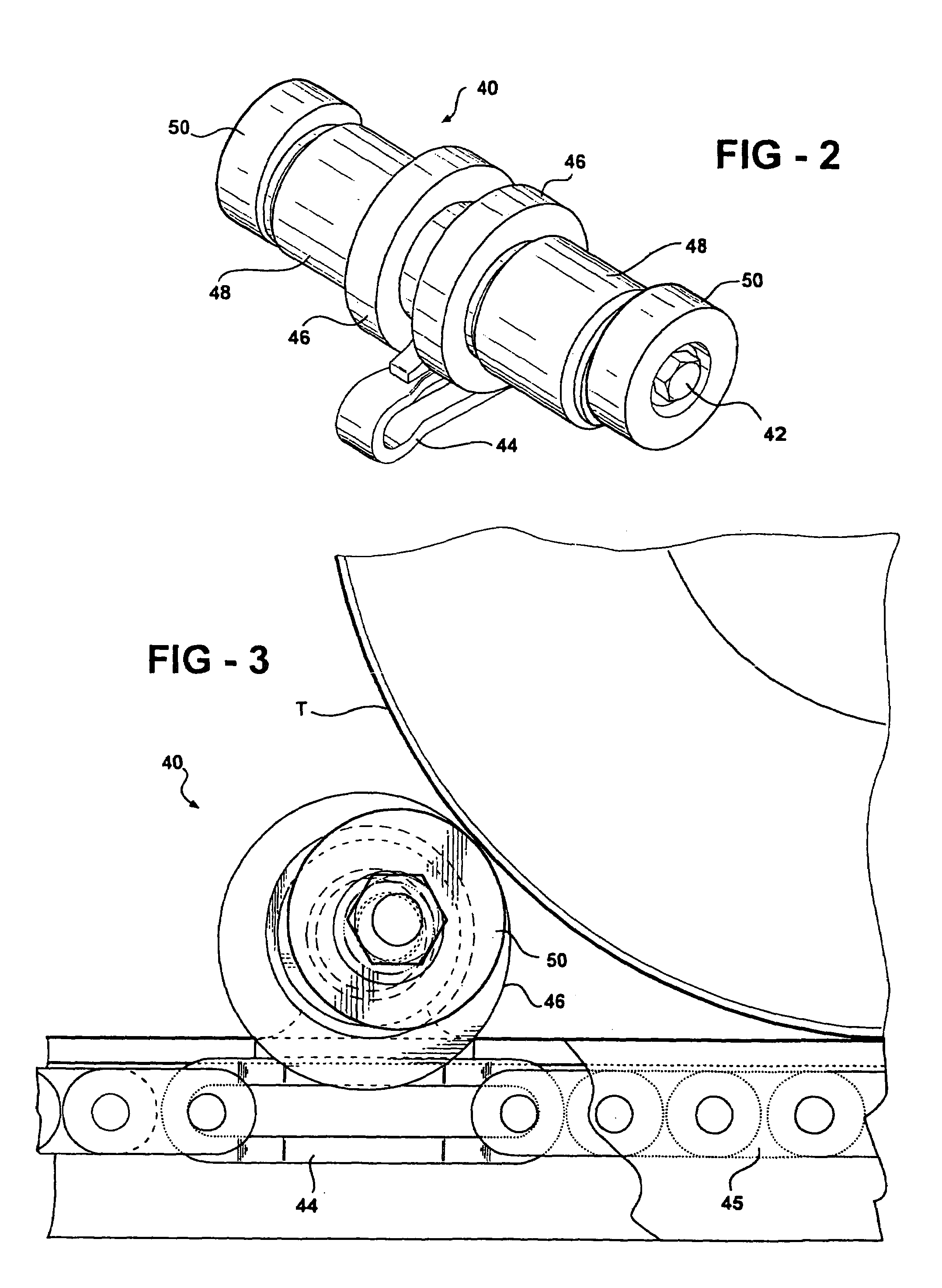
[0028]Referring to FIGS. 1 and 6, a three-tier auto-laundry conveyor 10 is shown to comprise a welded steel combination of vertical angle iron supports 12 joined at desired intervals by box section cross beams 13. A top track is made up of angle iron track rails 14 and 16 which are welded to the vertical supports 12 in longitudinally extending, parallel, spaced apart relationship to define a relatively narrow center slot 18; i.e., a slot of approximately two and one-half inches in width. The track rails 14 and 16 are adapted to support a vehicle tire T as shown in FIGS. 3, 6, 8 and 10 for rolling contact therewith.

[0029]Below the track rails 14 and 16, cantilever support arms 20 are welded and / or bolted to the vertical supports 12 and extend inwardly in reversely similar fashion to support intermediate angle iron track rails 22 and 24 which are also arranged in parallel spaced apart relationship to define a center slot of approximately two-and one-half inches in width. Unlike conven...


PUM


Abstract

An auto-laundry conveyor of three-tier design using upper, lower and intermediate track rails with a narrow slot between them. Dollies are provided in an endless loop conveyor chain and each dolly comprises a combination of a center link, a pair of reversely similar tire engaging rollers, a pair of reversely similar track engaging rollers outboard of the tire engaging rollers and a pair of reversely similar stabilizing rollers outboard of the track engaging rollers. The stabilizing rollers are effectively larger in diameter; i.e., higher than the track engaging rollers so as to prevent rolling contact between the stabilizing rollers and the track surface and to receive the tread surface of an off-center tire and keep the tread surface from interfering with rolling movement of the track engaging rollers. The conveyor is manufactured in 10-foot lengths except for the entry and exit sections which are of lengths X and Y wherein X plus Y equals 10 feet. An open track structure is used to prevent the accumulation of dirt and debris.

Description

RELATED APPLICATION[0001]This application is a continuation of U.S. application Ser. No. 10 / 835,210 filed on Apr. 28, 2004, now abandoned.FIELD OF THE INVENTION[0002]This invention relates to auto-laundry conveyors of the type employing an endless loop chain linking a plurality of dollies which roll along slotted tracks in both the vehicle conveying and return directions.BACKGROUND OF THE INVENTION[0003]In auto-laundries, otherwise known as car washes, it is known to use endless chain conveyors of the type having “dollies” linked into the chain at regular intervals. The dollies are used to push vehicles along the conveyor by engaging the tread surface of a tire. To function properly dollies must have tire engaging rollers and track engaging rollers. Typically the tire engaging rollers are larger in diameter than the track engaging rollers and are disposed in a center slot between opposite longitudinally extending track rails. The dollies include an axle member on which the rollers a...

Claims


Application Information

Patent Timeline
Patent Type & Authority Patents(United States)
IPC IPC(8): B61B7/00
CPCB60S3/004B65G21/2072
Inventor BELANGER, MICHAEL J.TURNER, BARRY S.TOGNETTI, DAVID L.
Owner PISTON OPW INC
Why Eureka
Try Eureka