Foldable bicycle frame

a bicycle frame and folding technology, applied in the field of bicycle frames, can solve the problems of prone to vibrating by an external force accidentally, inconvenient carrying, and the structure of the foldable bicycle frame, and achieve the effect of convenient folding up and locking

Inactive Publication Date: 2007-07-17
HUANG KUO MING
View PDF3 Cites 23 Cited by
  • Summary
  • Abstract
  • Description
  • Claims
  • Application Information

AI Technical Summary

Benefits of technology

[0007]The present invention has been accomplished under the circumstances in view. It is the main object of the present invention to provide a foldable bicycle frame that can easily be folded up and locked in the folded non-operative position convenient for carrying by hand or pulling on the ground by the user.
[0008]It is another object of the present invention to provide a foldable bicycle frame that keeps the whole structure steady for riding safely when set in the extended operative position.

Problems solved by technology

However, when the foldable bicycle frame 70 is folded up, the folded top tube 71 is not locked in the folded position and tends to be vibrated by an external force accidentally.
Further, when the foldable bicycle frame 70 is folded up, the two parts of the folded top tube 71 is not kept in parallel, i.e., a big contained angle is defined between the two parts of the folded top tube 71 and the front wheel and rear wheel of the folded bicycle frame 70 are not kept in parallel, resulting in a carrying inconvenience.
Further, this structure of foldable bicycle frame 70 still occupies much storage space when folded up.

Method used


Image

  • Foldable bicycle frame
  • Foldable bicycle frame
  • Foldable bicycle frame

Examples


first embodiment

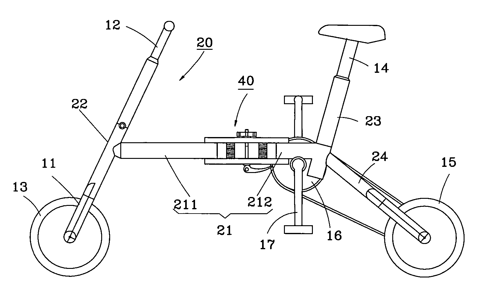
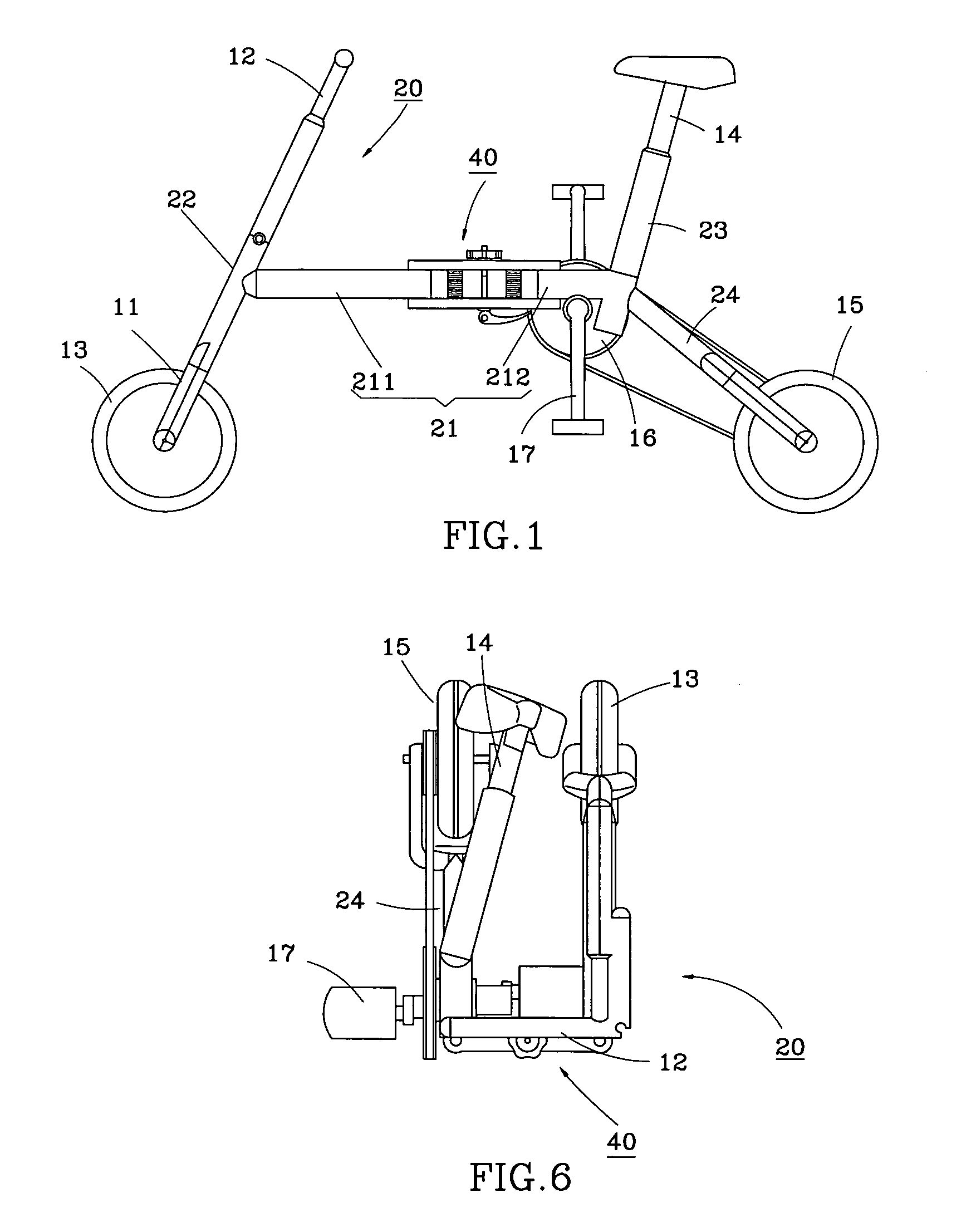
[0024]Referring to FIG. 1, a foldable bicycle frame 20 in accordance with the present invention is shown comprising a top tube 21, a head tube 22 at the front side of the top tube 21, a seat tube 23 at the rear side of the top tube 21, a rear fork assembly 24 obliquely backwardly extending from the bottom side of the seat tube 22 and supporting a rear wheel 15, a front fork 11 pivotally coupled to the head tube 22 at the bottom side and holding a front wheel 13, a handlebar 12 pivotally coupled to the head tube 22 at the top side and fixedly connected to the front fork 11, a seat pillar 14 fastened to the seat tube 23, a folding structure 40 installed in the top tube 21, and a chain drive formed of a chain wheel 16 and a pedal mechanism 17 and the related parts for pedaling by the bicycle rider to rotate the rear wheel 15.

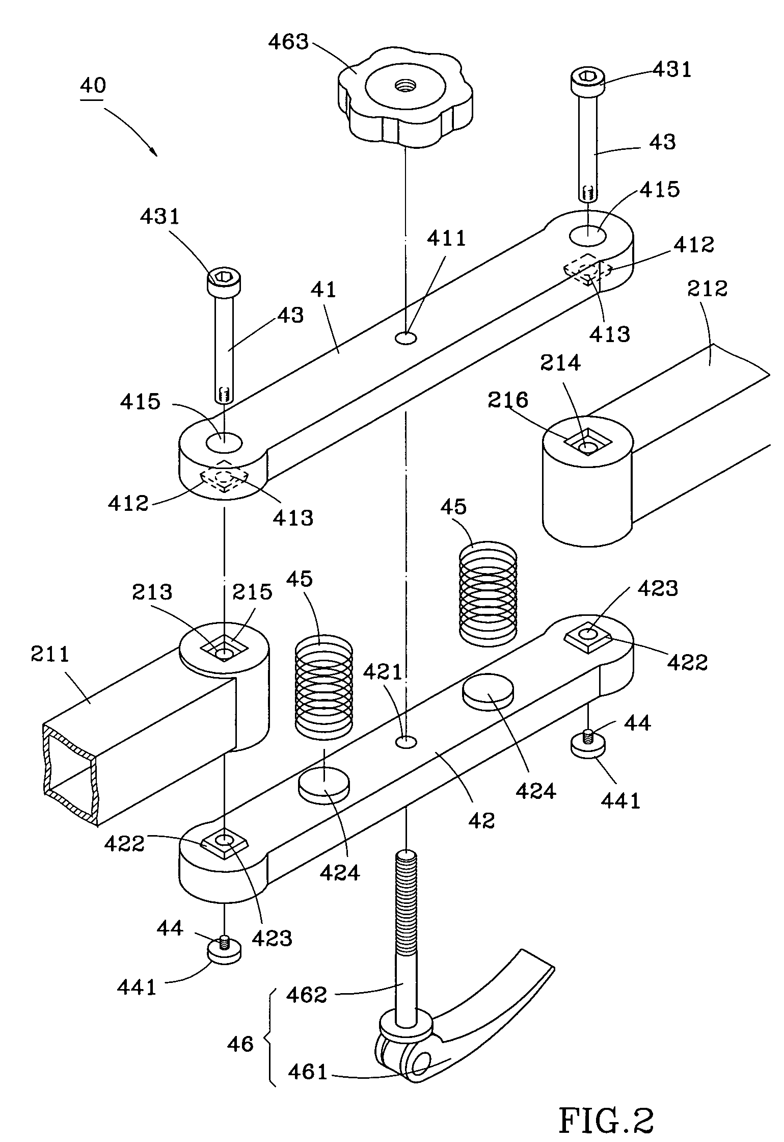
[0025]Referring to FIG. 2, the folding structure 40 controls folding of the top tube 21. The top tube 21 is comprised of a front top tube 211 and a rear top tube 2...

second embodiment

[0035]FIGS. 7-9 show a foldable bicycle frame according to the present invention. According to this embodiment, the folding structure, referenced by 50, comprises a top connecting bar 53, a bottom connecting bar 54, two pins 43, two screw members 44, a spring member 45, and a lock screw 55. The front top tube 51 and the rear top tube 52 each have two crossed locating grooves 511 or 512 respectively disposed at the top and bottom sides of the rear or front end thereof. The top connecting bar 53 and the bottom connecting bar 54 each have two crossed locating ribs 531 protruded from the bottom or top side near the two distal ends for engagement with the crossed locating grooves 511 of the front top tube 51 and the crossed locating grooves 512 of the rear top tube 52 respectively. Further, the spring member 45 is supported between the top connecting bar 53 and the bottom connecting bar 54. The locating mechanism, namely, the lock screw 55 has a threaded shank 511 inserted through the to...

third embodiment

[0036]FIGS. 10 and 11 show a foldable bicycle frame according to the present invention. According to this embodiment, the folding structure, referenced by 60, comprises a top connecting bar 64, a bottom connecting bar 65, a plurality of spring members 63, two pins 43, two screw members 44, and a locking mechanism 46. The front top tube 51 and the rear top tube 52 each have a plurality of vertical through holes 612 or 622 in the respective coupling end 611 or 621. The spring members 63 are respectively inserted through the through holes 612 and 622 of the front top tube 51 and the rear top tube 52 and stopped between the top connecting bar 64 and the bottom connecting bar 65 to force the connecting bars 64 and 65 away from the front top tube 51 and the rear top tube 52. Because the spring members 63 are kept in the through holes 612 and 622 of the front top tube 51 and the rear top tube 52, the whole structure of the locking mechanism 60 causes a sense of beauty.


PUM


Abstract

A foldable bicycle frame includes top and bottom connecting bars respectively pivotally connected between front and rear top tubes of the bicycle, a plurality of springs supported between the top and bottom connecting bars for pushing the top and bottom connecting bars vertically away from each other for allowing the front top tube and the rear top tube to be turned relative to each other between an operative position and a non-operative position, and a locking mechanism controlled by a locking lever to lock the top connecting bar and the bottom connecting bar in a position where the front top tube and the rear top tube aren't movable relative to each other.

Description

BACKGROUND OF THE INVENTION[0001]1. Field of the Invention[0002]The present invention relates to a bicycle frame and more particularly, to a foldable bicycle frame that can conveniently be carried by the user when it is set in the folded non-operative position.[0003]2. Description of the Related Art[0004]FIG. 13 shows a foldable bicycle frame according to the prior art. According to this design, the foldable bicycle frame 70 comprises a top tube 71, a folding structure 80 coupled between the two parts of the top tube 71, a head tube 72 at one end of the top tube 71, a seat tube 73 at the rear end of the top tube 71, seat stays 74 obliquely backwardly extended from the seat tube 73, and chain stays 75 connected to the seat stays 74. Further, the head tube 72 holds a front fork with a handlebar at the top and a front wheel the bottom (not shown). The seat tube 73 supports a seat pillar with a saddle (not shown). Further, a rear wheel (not shown) is pivotally provided at the connection...

Claims


Application Information

Patent Timeline
Patent Type & Authority Patents(United States)
IPC IPC(8): B62K19/02B62K15/00B62K17/00
CPCB62K15/006
Inventor HUANG, KUO-MING
Owner HUANG KUO MING
Why Eureka
Try Eureka