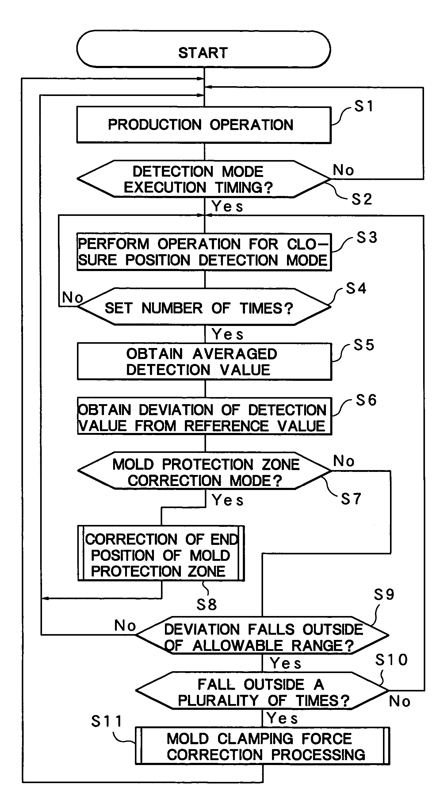
Mold protection method for mold clamping apparatus

a mold clamping and protection method technology, applied in the direction of auxillary shaping apparatus, manufacturing tools, food shaping, etc., can solve the problems of deterioration in quality, inability to detect anomalies such as the presence of foreign objects, and inability to detect anomalies

Active Publication Date: 2007-07-17
NISSEI PLASTIC IND CO LTD
View PDF9 Cites 2 Cited by
  • Summary
  • Abstract
  • Description
  • Claims
  • Application Information

AI Technical Summary

Benefits of technology

[0010]An object of the present invention is to provide a mold protection method for a mold clamping apparatus, which method can avoid the problems of impossibility of detection of an anomaly such as present of a foreign object or erroneous detection, even under a condition that a thin product is molded and the closed point of a mold is detected on the basis of change in a physical quantity.
[0011]Another object of the present invention is to provide a mold protection method for a mold clamping apparatus, which method can accurately detect a closed position of a movable platen, and eliminates the necessity for mold-thickness detection means, such as a scale and a position detector, for directly detecting the thickness of a mold, to thereby lower cost through reduction in the number of parts, and prevent the structure around a mold from becoming complex.

Problems solved by technology

Incidentally, unlike a direct-pressure-application-type mold clamping apparatus, because of its operation principle, a toggle-type mold clamping apparatus has a drawback in that slight expansion or contraction of a mold and tie bars, stemming from disturbing factors such as heating temperature of the mold and ambient temperature, causes a considerable change in mold clamping force, which results in deterioration in quality, in particular at the time of molding of precision products. FIG. 11 shows a change in mold clamping force Fm with time for the case where the correct value (target value) of mold clamping force Fm is 400 kN.
Due to its light weight, such a molded product is likely to adhere to the inner surface of the mold by means of static electricity.
However, even in the case where the end position of the mold protection zone is accurately set so as to meet the above-described requirements, when the above-described thermal expansion of a mold and that of tie bars occur upon an increase in temperature of the mold, the closed point of the mold shifts forward or rearward, whereby detection of an anomaly such as presence of a foreign object becomes impossible or erroneous detection occurs, under a certain condition that a thin product is molded and the closed point of the mold is detected on the basis of change in a physical quantity.

Method used


Image

  • Mold protection method for mold clamping apparatus
  • Mold protection method for mold clamping apparatus
  • Mold protection method for mold clamping apparatus

Examples


Embodiment Construction

[0024]An embodiment of the present invention will next be described in detail with reference to the drawings. The accompanying drawings are illustrative of the embodiment and are not meant to limit the scope of the invention. In order to describe the invention clearly, detailed description of known parts is omitted.

[0025]First, the structure of a toggle-type mold clamping apparatus Mc to which a mold protection method according to the present embodiment can be applied will be described with reference to FIGS. 7 and 8.

[0026]FIG. 7 shows an injection molding machine M including a toggle-link-type mold clamping apparatus Mc and an injection apparatus Mi. The mold clamping apparatus Mc includes a stationary platen 11 and a pressure-receiving platen 6 which are separated from each other. The stationary platen 11 is fixedly mounted on an unillustrated machine base, and the pressure-receiving platen 6 is mounted on the machine base in such a manner that it can advance and retract. Four tie...


PUM

PropertyMeasurementUnit
mold clamping force Fmaaaaaaaaaa
physical quantityaaaaaaaaaa

Abstract

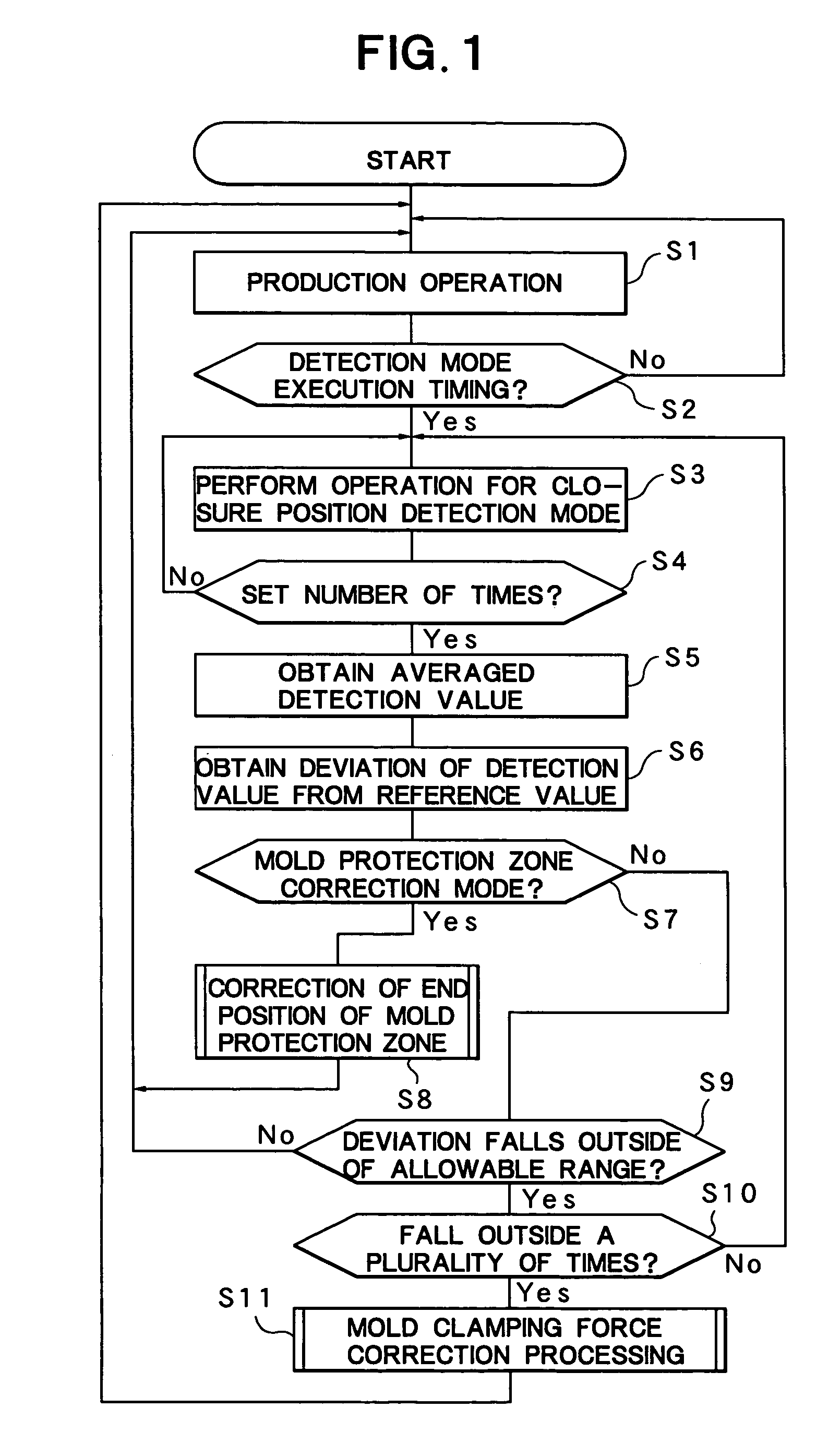
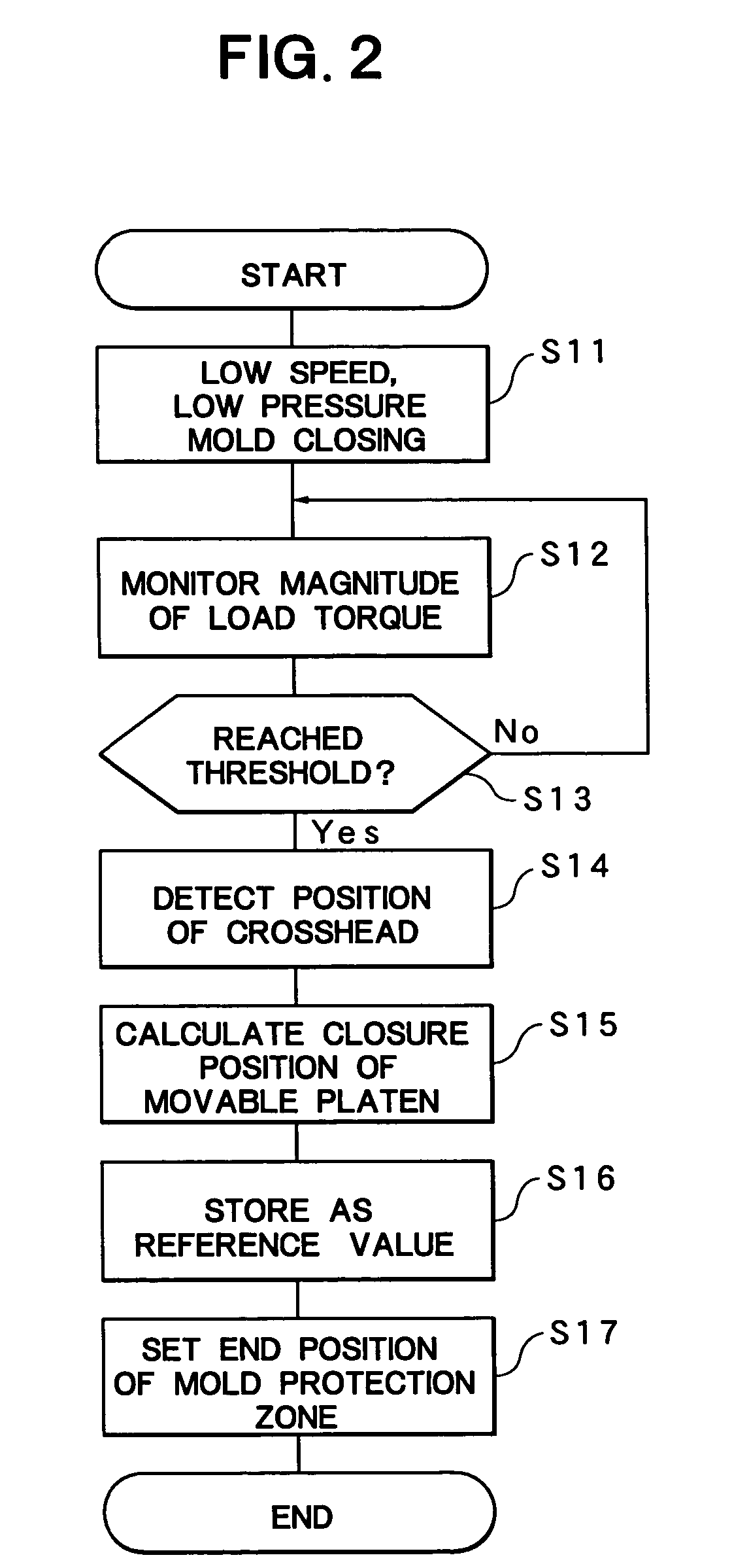
In a mold protection method for a mold clamping apparatus, a predetermined mold protection zone is set in a zone in which a mold is closed, and an anomaly such as presence of a foreign object is detected on the basis of a change in a physical quantity in the mold protection zone so as to protect the mold. The method includes the steps of previously setting, as a reference position, a closed position of a movable platen at which a target mold clamping force is obtained; setting an end position of the mold protection zone with respect to the reference position; obtaining, during a production operation, an actual closed position (detected position) of the movable platen; and correcting the end position of the mold protection zone on the basis of a deviation between the detected position and the reference position.

Description

BACKGROUND OF THE INVENTION[0001]1. Field of the Invention[0002]The present invention relates to a mold protection method for a mold clamping apparatus, which method detects an anomaly such as presence of a foreign object on the basis of a change in a physical quantity in a mold protection zone.[0003]2. Description of the Related Art[0004]A conventional toggle-type mold clamping apparatus for clamping a mold of an injection molding machine is disclosed in, for example, Japanese Patent Publication (kokoku) No. 6(1994)-61806. As disclosed in this publication, a toggle-type mold clamping apparatus includes a toggle mechanism which connects a movable platen for supporting a movable mold half and a crosshead advanced and retracted by a drive unit, and has a function of transmitting pressing force of the crosshead to the movable platen while amplifying the force. In such a mold clamping apparatus, when the toggle mechanism is completely extended, a predetermined mold clamping force determ...

Claims


Application Information

Patent Timeline
Patent Type & Authority Patents(United States)
IPC IPC(8): B29C45/64B29C45/80B29C45/66B29C45/76B29C45/84
CPCB29C45/661B29C45/844
Inventor HAKODA, TAKASHIMIYAJIMA, MASAHIKO
Owner NISSEI PLASTIC IND CO LTD
Why Eureka
Try Eureka