System and method for providing lifeline telecommunication service to line-powered customer premises equipment

Active Publication Date: 2007-07-17
GENBAND US LLC
View PDF95 Cites 12 Cited by
  • Summary
  • Abstract
  • Description
  • Claims
  • Application Information

AI Technical Summary

Benefits of technology

[0008]In accordance with the present invention, a system and method for providing lifeline telecommunication service to line-powered customer premis

Problems solved by technology

Unfortunately, existing VoDSL networks may not provide the degree of reliability necessary to enable true integration of telephony and data services.
Because of these architectural li

Method used


Image

  • System and method for providing lifeline telecommunication service to line-powered customer premises equipment
  • System and method for providing lifeline telecommunication service to line-powered customer premises equipment
  • System and method for providing lifeline telecommunication service to line-powered customer premises equipment

Examples


Example

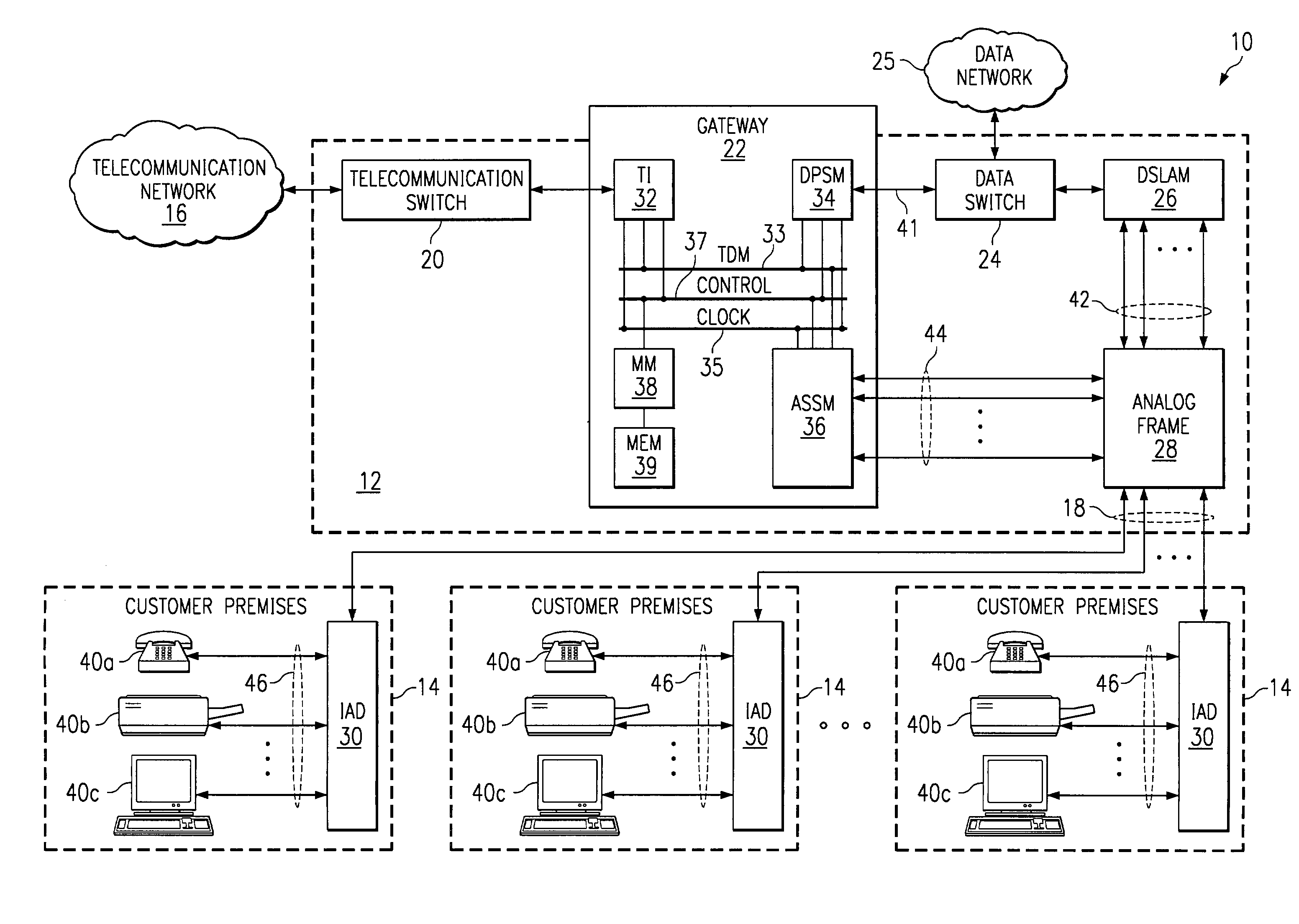
DETAILED DESCRIPTION OF THE DRAWINGS

[0027]FIG. 1 illustrates a system 10 for communicating telecommunication information between telecommunications network 16 and customer premises equipment 14 using local loop circuits 18. Telecommunication network 16 may be a public switched telephone network (PSTN), a private switched telephone network, or any other interconnected collection of telecommunication switches that provide local, long distance, or international telephone service. Telecommunication information includes voice, data, image, video, or any other type of information that may be communicated over telecommunication network 16. In a particular embodiment, local loop circuits 18 are twisted pair lines between network equipment 12 and customer premises equipment 14.

[0028]In operation, network equipment 12 and customer premises equipment 14 communicate telecommunication information over local loop circuit 18 using either data packets or an analog telephone signal. In a normal mode...


PUM


Abstract

A system for providing lifeline telecommunication service includes a telecommunication interface, a data packet service module, an analog signal service module, a power generator, and a switch. The telecommunication interface receives telecommunication information from a telecommunication switch. The data packet service module receives the telecommunication information from the telecommunication interface and generates data packets for communicating the telecommunication information over a local loop circuit in a first mode of operation. The analog signal service module receives the telecommunication information from the telecommunication interface and generates an analog signal for communicating the telecommunication information over the local loop circuit in a second mode of operation. The power generator generates a first voltage. The switch selects the first voltage for communication to the local loop circuit in the first mode of operation and selects the analog signal for communication to the local loop circuit in the second mode of operation.

Description

TECHNICAL FIELD OF THE INVENTION[0001]This invention relates generally to the field of telecommunications and, more particularly, to a system and method for providing lifeline telecommunication service to line-powered customer premises equipment.CROSS-REFERENCE TO RELATED APPLICATIONS[0002]This application is related to U.S. application Ser. No. 09 / 502,668, filed on Feb. 11, 2000, by Peter J. Renucci, et al. and entitled, “System and Method for Communicating Telecommunication Information Between Customer Premises Equipment and Network Equipment,”.[0003]This application is related to U.S. application Ser. No. 09 / 502,670, filed on Feb. 11, 2000, by Peter J. Renucci, et al. and entitled, “System and Method for Communicating Telecommunication Information Between a Telecommunication Switch and Customer Premises Equipment,”.[0004]This application is related to U.S. application Ser. No. 09 / 502,369, filed on Feb. 11, 2000, by Peter J. Renucci, et al. and entitled, “System and Method for Com...

Claims


Application Information

Patent Timeline
IPC IPC(8): H04J1/16H04J3/16H04L12/66
CPCH04Q11/04H04Q2213/13039H04Q2213/13082H04Q2213/13166H04Q2213/13202
Inventor RENUCCI, PETER J.
Owner GENBAND US LLC
Why Eureka
Try Eureka