Acquisition mechanism for a mobile satellite system

a satellite system and acquisition mechanism technology, applied in the field of signal synchronization, can solve the problems of time delay, 320 msec window the 5 msec waveform, and the mobile terminal does not know at what time, so as to enable the synchronization of the communications terminal

Inactive Publication Date: 2007-07-17
HUGHES NETWORK SYST
View PDF9 Cites 50 Cited by
  • Summary
  • Abstract
  • Description
  • Claims
  • Application Information

AI Technical Summary

Benefits of technology

[0024]In one embodiment, the present invention can be characterized as a method for enabling synchronization of a communications terminal in a wireless communication system comprising the step of receiving a burst at a receiver of the communications terminal, the burst containing a composite waveform including two or more component waveforms, wherein each of the two or more waveforms has a known frequency variation throughout the burst. The composite waveform has a composite bandwidth on an order of an available channel bandwidth, and wherein each of said two or more component waveforms has a component bandwidth on the order of the available channel bandwidth. Additionally, a range of values for the differences between the instantaneous frequencies of two of said two or more component waveforms is on an order of twice of said available channel bandwidth.
[0025]In another embodiment, the present invention may be characterized as an acquisition system of a wireless communications terminal for acquiring a received composite waveform including two or more component waveforms and estimating a frequency offset and a timing offset of the received composite waveform. The acquisition system includes a first phase shifter for desweeping a first component waveform of the received composite waveform and a first processor coupled to the first phase shifter for transforming the first component waveform having been deswept into a first frequency domain representation. Furthermore, the acquisition system includes a second phase shifter for desweeping a second component waveform of said received composite waveform and a second processor coupled to the second phase shifter for transforming the second component waveform, having been deswept, into a second frequency domain representation. Furthermore, a detection processor is coupled to said first processor for detecting a peak of said first frequency domain representation, thus, detecting the presence of said first component waveform. The detection processor includes a parameter estimator for computing said frequency offset and said timing offset of said received composite waveform, having been detected.
[0026]In a further embodiment, the present invention may be characterized as a method for enabling synchronization of a communications terminal in a wireless communication system comprising the steps of: receiving a burst at a receiver of the communications terminal, the burst containing a composite waveform including two or more component waveforms, wherein each of the two or more waveforms has a known frequency variation throughout the burst; detecting the presence of the composite waveform; and estimating a frequency offset and a timing offset of the composite waveform as received into said receiver, whereby synchronization is achieved.

Problems solved by technology

Furthermore, the mobile terminal does not know at what time within any given 320 msec window the 5 msec waveform will arrive.
However, because of signal degradation and distortions due to all forms of time delays, propagation delays, doppler shifting, and noise, it is necessary to compensate for the frequency and / or time shifting of the waveform.
By way of background, time delays result from several factors.
Time delays may be caused by obstructions in a dominant signal path that generate “multi-paths” to occur from scattered paths resulting from reflections off the obstructions.
The differences in distance between the multi-paths result in timing offsets as well as fading of the signal, depending upon the type of channel (e.g. Rician or Rayleigh fading).
Also, in mobile satellite communications systems, in particular, relative motion between the satellite and the mobile terminal due to a velocity of the satellite as it orbits the Earth and another velocity of the terminal as it is operated from a moving vehicle, for example, results in varying time delay by the signals traveling between the satellite and the mobile terminal.
However, if a building were blocking the line-of-sight path of the voice signal and attenuated the voice signal by 20 dB, then the mobile terminal could not receive the voice signal but could still track and receive an alerting signal from the satellite.
Thus, conditions supporting alert signals will not necessarily support voice signals in the same mobile satellite system.
Although sinusoidal waveforms or tones are easily detectable by mobile terminals, they present a problem of “spurs” in the received frequency when the tone travels in mobile terminal's hardware.
Furthermore, a receiver typically includes a variety of frequency sources that tend to induce sinusoids to the received signal (i.e. tone), making distinctions between the received signal and the induced sinusoids difficult to discern.
When spurs occur in the receiver, there can be a loss of synchronization because the waveform of interest (i.e. the tone) may be lost.
One way to avoid these spurs is to change RF hardware so that they are eliminated by the hardware, however this is costly and takes space and power within the hardware itself.
Although the QPSK modulated signal solves the problem of spurs, it does not solve the detectability of varying signal levels used in multiple levels of services, such as voice and alerting services.
Although the use of the tone followed by the modulated waveform solves the problem caused by induced spurs, it exhausts system resources such as power, bandwidth and time, and is not well-suited to two or more levels of service, such as alerting and voice communication.

Method used


Image

  • Acquisition mechanism for a mobile satellite system
  • Acquisition mechanism for a mobile satellite system
  • Acquisition mechanism for a mobile satellite system

Examples


Embodiment Construction

[0047]The following description of the presently contemplated best mode of practicing the invention is not to be taken in a limiting sense, but is made merely for the purpose of describing the general principles of the invention. The scope of the invention should be determined with reference to the claims.

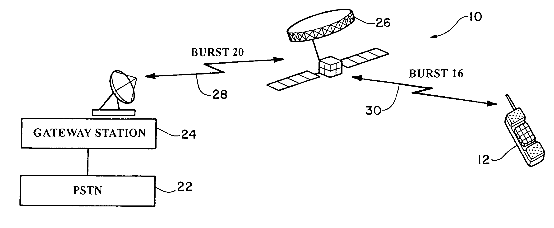
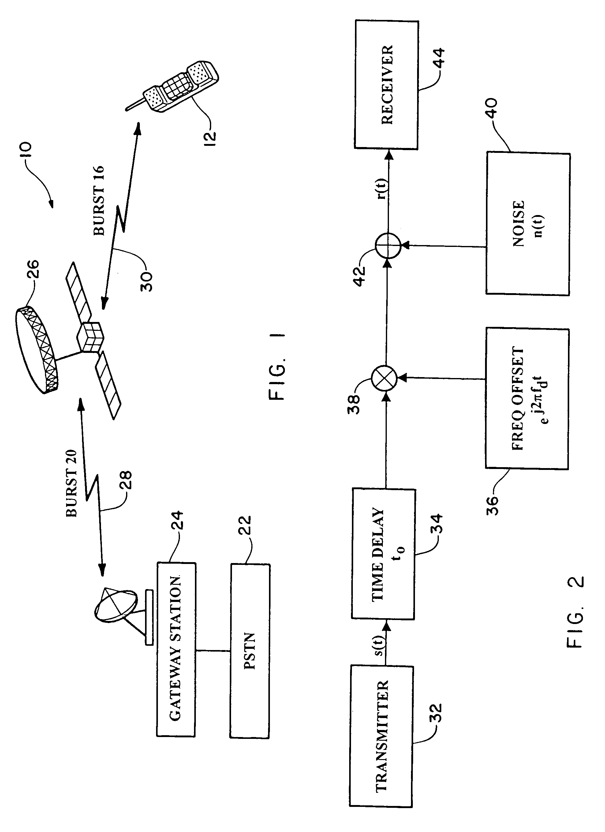
[0048]Referring first to FIG. 1, a block diagram of a typical satellite communications system is shown. The satellite communications system 10 includes a first communications terminal or a gateway station 24 (also referred to as a base station), second communications terminal or mobile terminal 12 (also referred to as a wireless terminal or wireless transceiver), a public switched telephone network (PSTN) 22, a satellite 26, and communications links 28 and 30. The satellite communications system 10 is one embodiment in which the present invention may be practiced. It is noted that the terms communications terminal, terminal, and transceiver are used synonymously.

[0049]The public sw...


PUM


Abstract

A method for enabling synchronization of a communications terminal in a wireless communication system, and a corresponding acquisition system of the communications terminal, wherein the method consists of the steps of: receiving a burst at a receiver of the communications terminal, the burst containing a composite waveform including two or more component waveforms, wherein each of the two or more waveforms has a known frequency variation throughout the burst; detecting the presence of the composite waveform; and estimating a frequency offset and a timing offset of the composite waveform as received into the receiver, whereby synchronization is achieved.

Description

[0001]This application claims priority under 35 U.S.C § 119(e) to U.S. Provisional Patent Application Ser. No. 60 / 109,671, filed Nov. 24, 1998, of Vishwanath et al., for ACQUISITION MECHANISM FOR A MOBILE SATELLITE SYSTEM, which U.S. Provisional Patent Application is incorporated herein by reference.[0002]This application is related to U.S. Patent Application Ser. No. 09 / 447,685, filed concurrently herewith Nov. 23, 1999, of Vishwanath et al., for WAVEFORM SUPPORTING SYNCHRONIZATION IN MOBILE SATELLITE SYSTEMS; now U.S. Pat. No. 6,418,158, which is incorporated herein by reference.BACKGROUND OF THE INVENTION[0003]The present invention relates to signal synchronization, and more particularly to signal synchronization in a communications system. Even more particularly, the present invention relates to synchronization of wireless transceivers by transmitting a composite waveform having a known frequency variation to an unsynchronized wireless transceiver of a mobile satellite communica...

Claims


Application Information

Patent Timeline
Patent Type & Authority Patents(United States)
IPC IPC(8): H04B7/00
CPCH04B7/18532H04B1/69H04B2001/6912
Inventor VISHWANATH, T GPARR, MICHAELSHI, ZHEN-LIANGERLICH, SIMHA
Owner HUGHES NETWORK SYST
Why Eureka
Try Eureka