Ceramic packing element

a packing element and ceramic technology, applied in the field of packing elements, can solve the problems of significant loss of material in the bed, limited use of the open structure alone,

Inactive Publication Date: 2007-07-24
SAINT GOBAIN CERAMICS & PLASTICS INC
View PDF24 Cites 17 Cited by
  • Summary
  • Abstract
  • Description
  • Claims
  • Application Information

AI Technical Summary

Problems solved by technology

This is promoted by very open structures but open structure alone is of limited use if the elements in the tower nest together such that parts of one packing element penetrate within the space of a second element.
Such entrainment or abrasion typically causes significant losses to the material in the bed.

Method used


Image

  • Ceramic packing element
  • Ceramic packing element
  • Ceramic packing element

Examples


Embodiment Construction

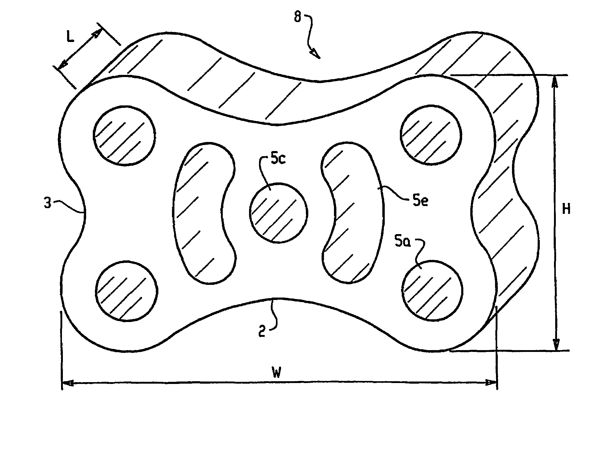
[0018]A solid ceramic packing element is provided having an essentially uniform cross-section along an axis of symmetry in the direction of extrusion defining the length of the element. The element has first and second concave external surfaces at the ends of height and width axes respectively perpendicular to the length direction. The concave surfaces are connected by convex surfaces. The element is provided with a plurality of through passages in the length direction.

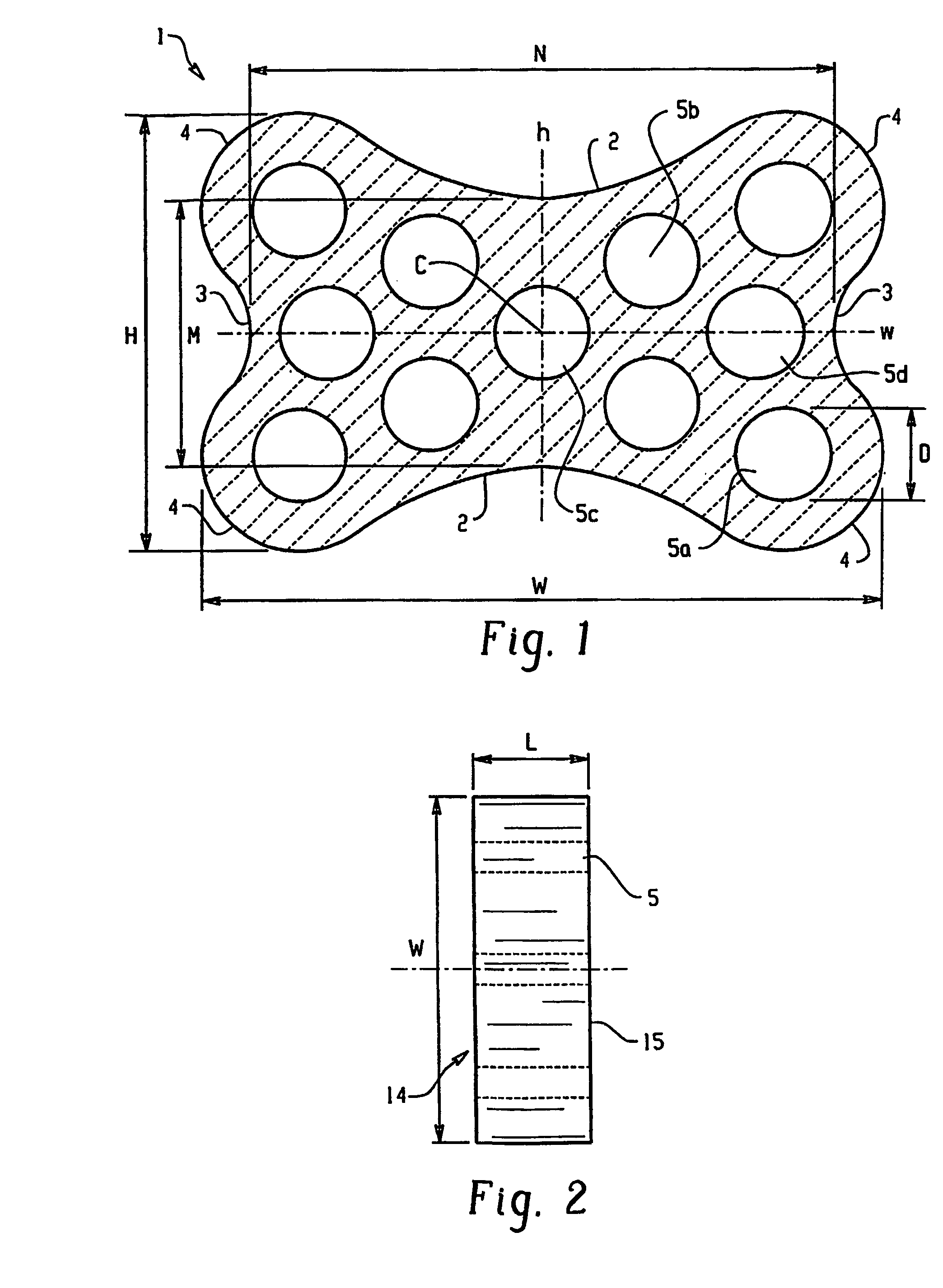
[0019]The invention is now more particularly described with reference to the embodiment illustrated in FIG. 1. This is not intended to imply any necessary limitations in the scope of the invention because it will be readily appreciated that many minor variations could be made without departing from the essential spirit of the invention.

[0020]In FIG. 1 a bed limiter packing element 1 is shown in cross-section along the length dimension. The element has a width dimension W, parallel to the width axis w, and a height dim...


PUM

PropertyMeasurementUnit
angleaaaaaaaaaa
angleaaaaaaaaaa
lengthaaaaaaaaaa

Abstract

The invention provides an improved ceramic packing element (1, 6, 8) suited to use as a bed limiter having a generally uniform cross-section in the length (l) direction with the basic shape of a bow-tie and having a plurality of through passages (5) parallel to the length dimension (L).

Description

[0001]This application is the U.S. national phase entry of PCT / US03 / 17994, filed Jun. 9, 2003, and claims priority as a continuation in part, of U.S. application Ser. No. 10 / 167,893, filed Jun. 12, 2002, now abandoned, the disclosures of which are incorporated in their entireties, by reference.BACKGROUND OF THE INVENTION[0002]1. Field of the Invention[0003]The invention relates to packing elements of the type that are often called “random” or “dumped” packings, and will be described with particular reference thereto. However, it will be appreciated that the elements have applications in other areas.[0004]2. Discussion of the Art[0005]Random or dumped packings are used to fill towers units in which mass or heat transfer or any chemical reaction processes occur. A particularly important application is the use of such ceramic elements in heat recovery operations where it is necessary to provide maximum effective contact with hot fluids passing through the reactor. Another key factor in...

Claims


Application Information

Patent Timeline
Patent Type & Authority Patents(United States)
IPC IPC(8): B01F3/04B01D47/00B01J19/30
CPCB01J19/30Y10T428/24479B01J2219/30223B01J2219/30242B01J2219/30246B01J2219/30296B01J2219/30416B01J2219/30475B01J2219/312B01J2219/3183B01J2219/3185B01J2219/3188Y10S261/72Y10T428/24273B01J2219/30203B01J19/00
Inventor NIKNAFS, HASSAN S.ROBINETTE, RICHARD N.DAHAR, STEPHEN L.SZYMANSKI, THOMASREID, JOHN S.
Owner SAINT GOBAIN CERAMICS & PLASTICS INC
Why Eureka
Try Eureka