
Fixing member comprising an integrity control system

a technology of integrity control and fixing member, applied in the direction of screws, nuts, bolts, etc., can solve the problems of further restrictions on their use, complex and costly sealing devices that comprise electronic means, etc., and achieve the effect of easy and quick questioning and easy checkability

Inactive Publication Date: 2007-07-24
EURON COMMUNITY EC
View PDF10 Cites 28 Cited by
  • Summary
  • Abstract
  • Description
  • Claims
  • Application Information

AI Technical Summary

Benefits of technology

"The present invention aims to provide a fastening member with a reliable and easily checkable integrity system that can contain information that can be easily and quickly queried. The fastening member comprises a threaded part and a head with an electronic component that can remember and transmit information. The integrity of the device is ensured by the electronic component, which also acts as an indicator of the member. The fastening member is inexpensive and mechanically robust. The invention also includes a ring, grooves, and a shear pin to hold the electronic component in its housing and prevent it from being damaged during tightening or untightening. The electronic component can be a passive-type transponder or a transponder with power supply means. The data storage means of the electronic component can comprise data encryption means and be programmable or multi-page type. The invention also includes a second remotely interrogatable electronic component located in the cap outside the recessed portion, which ensures data can still be read even after the destruction of the first component."

Problems solved by technology

However, currently available sealing devices that comprise electronic means are complex and costly.
They are generally designed for a specific purpose and cannot be used with any type of object at will.
Furthermore, they are fragile in their mechanical structure, which makes them very vulnerable during handling and transport, a factor that places further restrictions on their use.

Method used


Image

  • Fixing member comprising an integrity control system
  • Fixing member comprising an integrity control system
  • Fixing member comprising an integrity control system

Examples


Embodiment Construction

[0028]In order to avoid unnecessarily complicating the description, the present invention will be described essentially in relation to a fastening member of screw bolt type. However, it will be clearly apparent that the present invention can be applied to any other type of fastening member that is put in place by tightening.

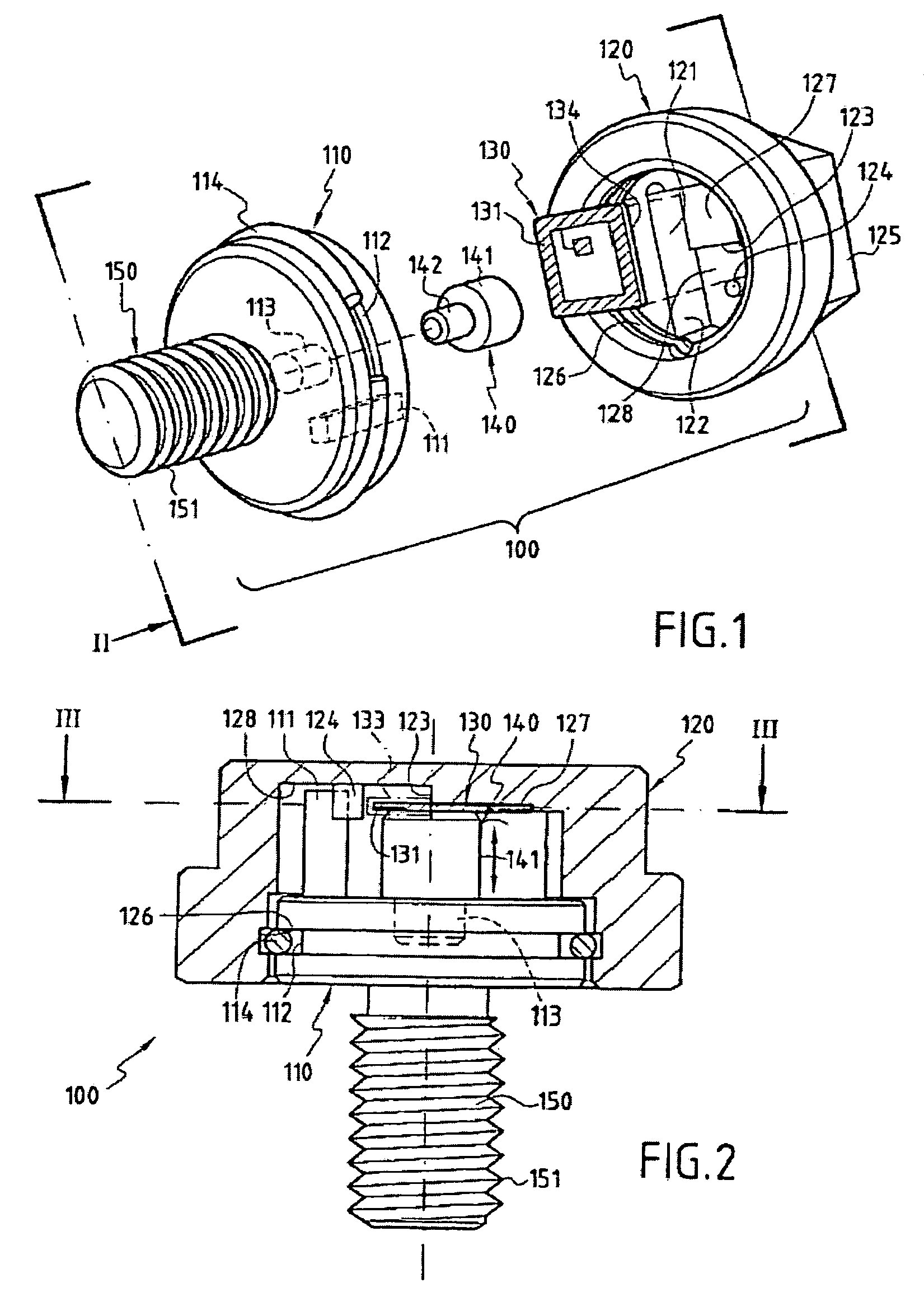
[0029]FIG. 1 shows the different elements that make up a form of embodiment of a fastening member according to the invention.

[0030]In this embodiment, the fastening member comprises a protruding part 150 comprising a screw thread 151 designed to cooperate with a nut or machined thread in a component or structure. The fastening member further comprises a head 100 formed principally of a plate 110 in one piece with the threaded part 150 and a cap 120 which is assembled with the plate and entirely covers it so as to form the external part of the head of the fastening member. For this purpose, the cap 120 comprises an upper part 125 of hexagonal shape able to coopera...


PUM


Abstract

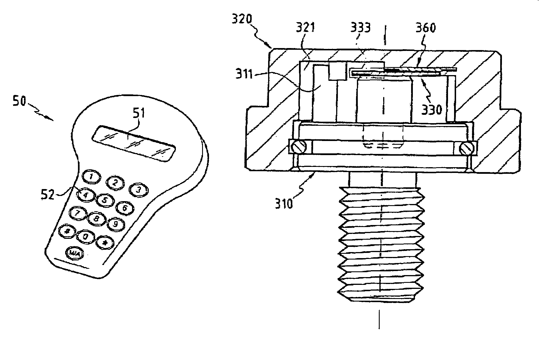
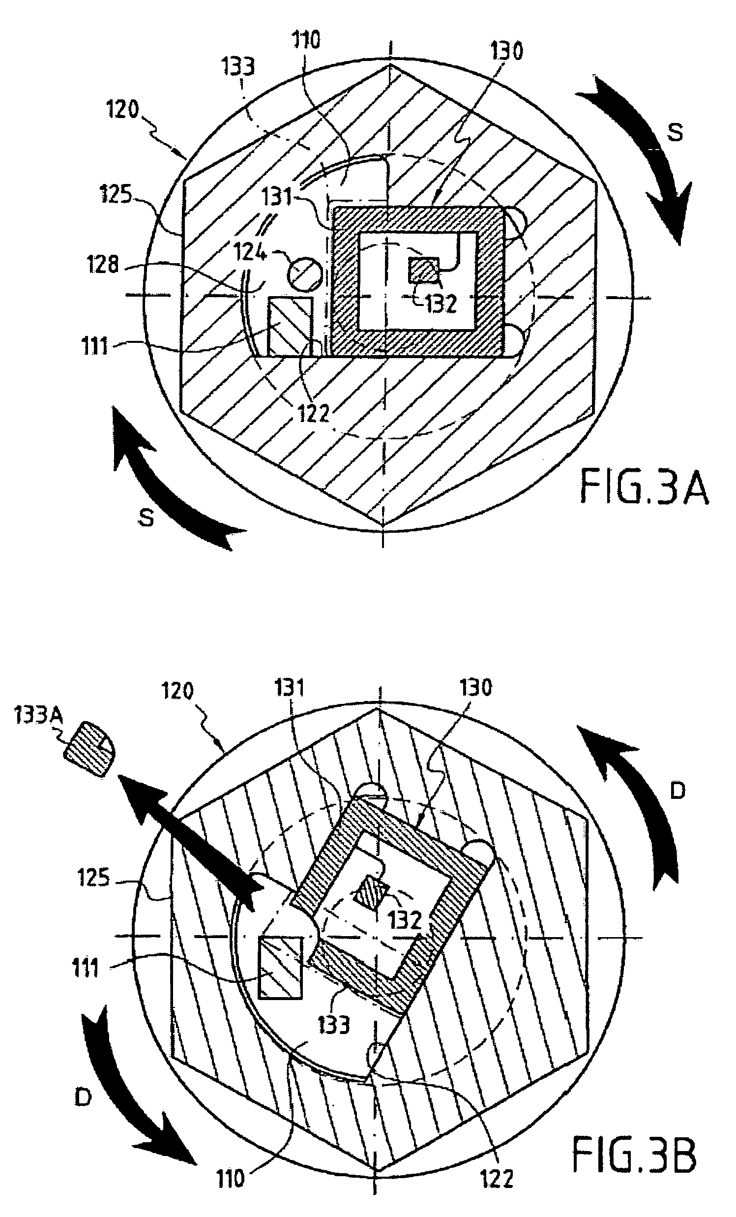
The invention concerns a fastening member comprising a threaded part (150) and a head (100) with which the threaded part can be turned in order to tighten the fastening member in a corresponding element. The head (100) is formed of a plate (110) in one piece with the threaded part (150) and a cap (120) covering said plate. The cap (120) comprises a recessed portion (121) in which an offset is provided to form a housing (128). The plate (110) comprises a guide finger (111) located inside the housing (128) to form a stop against which the cap presses in order to impart a rotational movement to the plate in the tightening direction. The cap (120) further comprises a remotely interrogatable electronic component (130) comprising a data storage means (132). Said component is held in the recessed portion (121) with its end (133) protruding into the housing (128) so as to strike against the guide finger (111) and cause the fracture of the component when any attempt is made to unscrew or untighten the fastening member.

Description

FIELD OF THE INVENTION [0001]The present invention concerns a fastening member of the screw or pin type the integrity of which can be verified electronically.BRIEF DESCRIPTION OF RELATED ART[0002]There are many solutions, both electronic and mechanical, for guaranteeing the integrity and checking for Unauthorized manipulation of substances (e.g. noxious, radioactive, etc.) during storage or transport. There are also solutions for verifying whether systems, such as motors, aircraft parts or similar, have been accessed or manipulated without authorization.[0003]The technologies employed for applying seals are very varied, and depend mainly on their use and the degree of security required.[0004]Thus, when the aim is simply to ensure the integrity of an object such as a container or a trunk, the function of the seal is to guarantee that the object has not been opened without authorization. In this case, inexpensive devices such as simple plastic or metal collars fixed to the opening dev...

Claims


Application Information

Patent Timeline
Patent Type & Authority Patents(United States)
IPC IPC(8): F16B41/00G09F3/00
CPCF16B41/005
Inventor AZZALIN, GRAZIANOKORN, CHRISTOPHEPOUCET, ANDRESIRONI, MARCO
Owner EURON COMMUNITY EC
Learn More