Bar for a warp knitting machine

A technology of warp knitting machine and bar, which is applied in the field of bar for warp knitting machine, which can solve the problem of high cost and achieve the effect of small quality, small resistance and small wear

Active Publication Date: 2009-02-18
KARL MAYER STOLL R&D GMBH
View PDF2 Cites 11 Cited by
  • Summary
  • Abstract
  • Description
  • Claims
  • Application Information

AI Technical Summary

Problems solved by technology

However, this method is relatively costly because the tools used for milling wear relatively quickly

Method used


Image

  • Bar for a warp knitting machine

Examples


Embodiment Construction

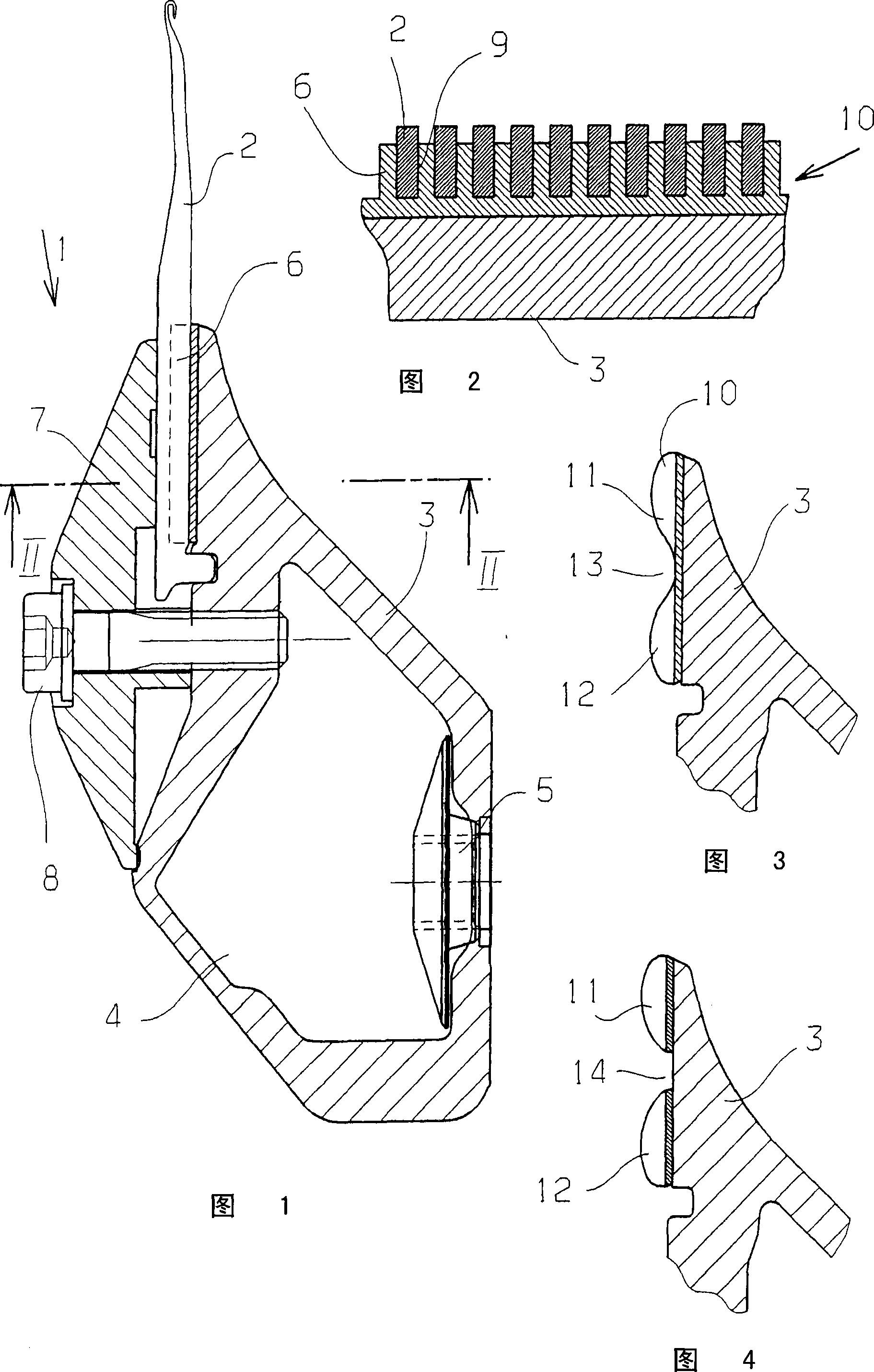
[0031] The needle bed 1 shown in FIG. 1 has knitting needles 2 . The needle bed 1 has a body 3 made of carbon fiber reinforced plastic material, which surrounds a cavity 4 and is provided with fixing means 5 for fixing the bar 1 in a weaving machine (not shown in detail).

[0032] The knitting needles 2 are arranged in the needle holder 6 and are held there by the cover plate 7 . The cover plate 7 is connected with the body 3 by bolts 8 . A plurality of such bolts 8 can of course be provided over the length of the bar 1 .

[0033] A groove 9 is provided for each needle 2 . This recess is formed in the plastic coating 10 in which the needle holder 6 is formed. The plastic coating 10 is made of a plastic that is adhesive in the uncured state, in particular a two- or more-component adhesive, which is formed as a synthetic resin or based on a polyurethane base.

[0034] The plastic coating is suitably applied using a pneumatically or hydraulically or otherwise driven glue appl...


PUM


Abstract

A bar (1) for a warp knitting machine comprises a corpus (3) which has a carbon fiber reinforced plastic material, and a needle receiver (6). In order to process the bar easily and with low cost, the needle receiver (6) is constructed in a plastic coating (10).

Description

technical field [0001] The invention relates to a bar for a warp knitting machine with a body having a carbon-fibre-reinforced plastic material and a needle holder. [0002] The invention also relates to a method of manufacturing a bar for a warp knitting machine, wherein a body of carbon fiber reinforced plastic material is provided with a needle holder. Background technique [0003] The bar installed in the warp knitting machine must generally be accelerated at least once in one direction of action and at least once in the opposite direction of action during a knitting cycle. In order to keep the forces necessary for acceleration small, efforts are made to keep the mass of the bar small. At the same time it is also desired to achieve a high mechanical robustness. This comb bar was therefore proposed several years ago: it has a body of carbon-fiber-reinforced plastic. Plastic materials reinforced with carbon fibers have a relatively low weight and relatively good mechani...

Claims


Application Information

Patent Timeline
Patent Type & Authority Applications(China)
IPC IPC(8): D04B27/06D04B27/24
CPCD04B27/24D04B27/06D04B15/20
Inventor K·米斯塔G·舒勒
Owner KARL MAYER STOLL R&D GMBH
Why Eureka
Try Eureka