Adjustable safety switch

a safety switch and adjustment technology, applied in the field of safety switches, can solve the problems of affecting the deformation of the bi-metallic plate, and increasing the cost of the product, so as to achieve the effect of controlling the bi-metallic pla

Inactive Publication Date: 2007-07-24
YU TSUNG MOU
View PDF39 Cites 26 Cited by
  • Summary
  • Abstract
  • Description
  • Claims
  • Application Information

AI Technical Summary

Benefits of technology

[0005]The main object of the present invention is to provide a safety switch that uses a link assembly connected with the switch member to effectively control the bi-metallic plate to move between “ON” and “OFF” positions.

Problems solved by technology

There are too many parts involved in the safety switch device and a longer period of time is required when assembling the switch device, this increases the cost of the products.
The parts might be arranged inaccurately and affects the deformation of the bi-metallic plate.

Method used


Image

  • Adjustable safety switch
  • Adjustable safety switch
  • Adjustable safety switch

Examples


Embodiment Construction

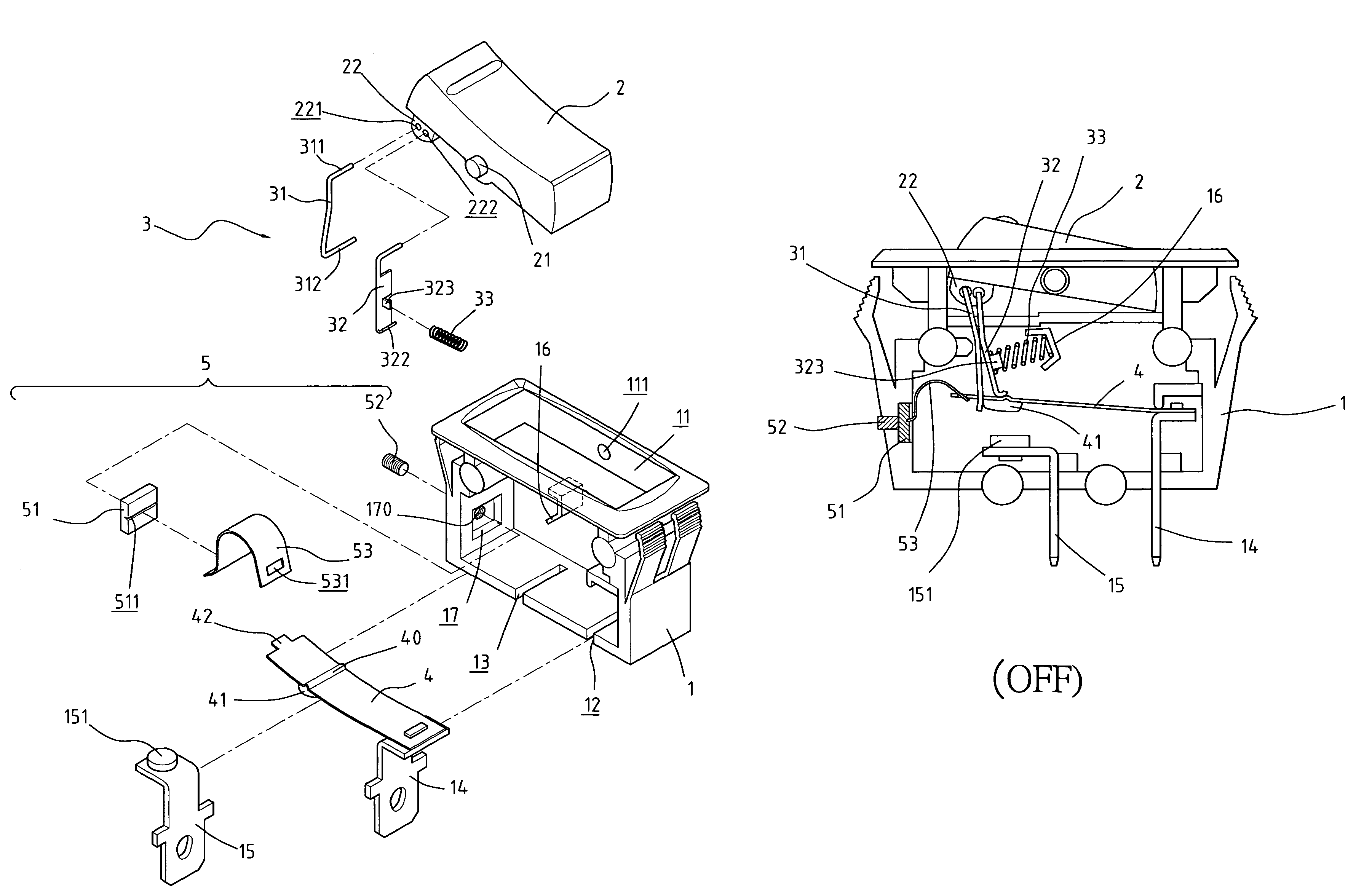
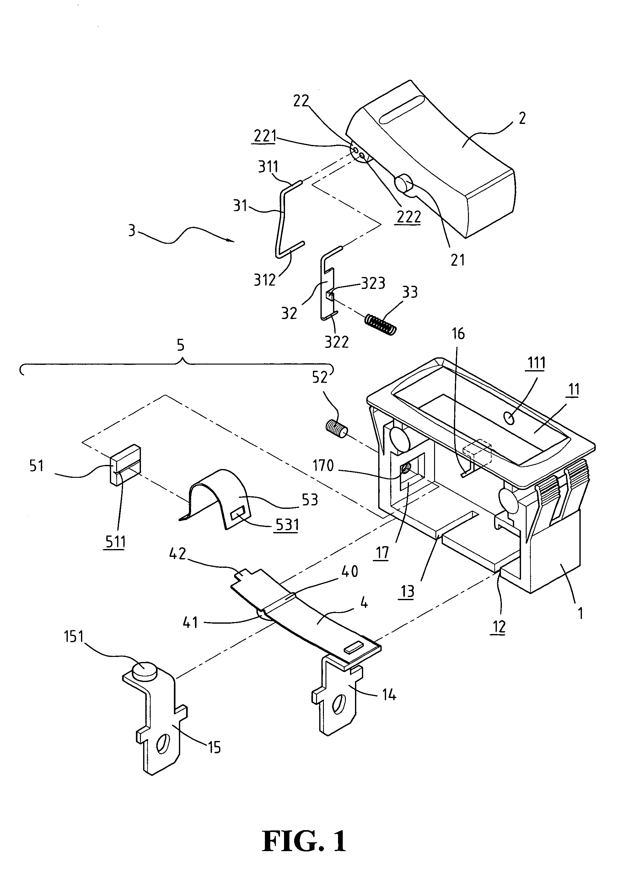
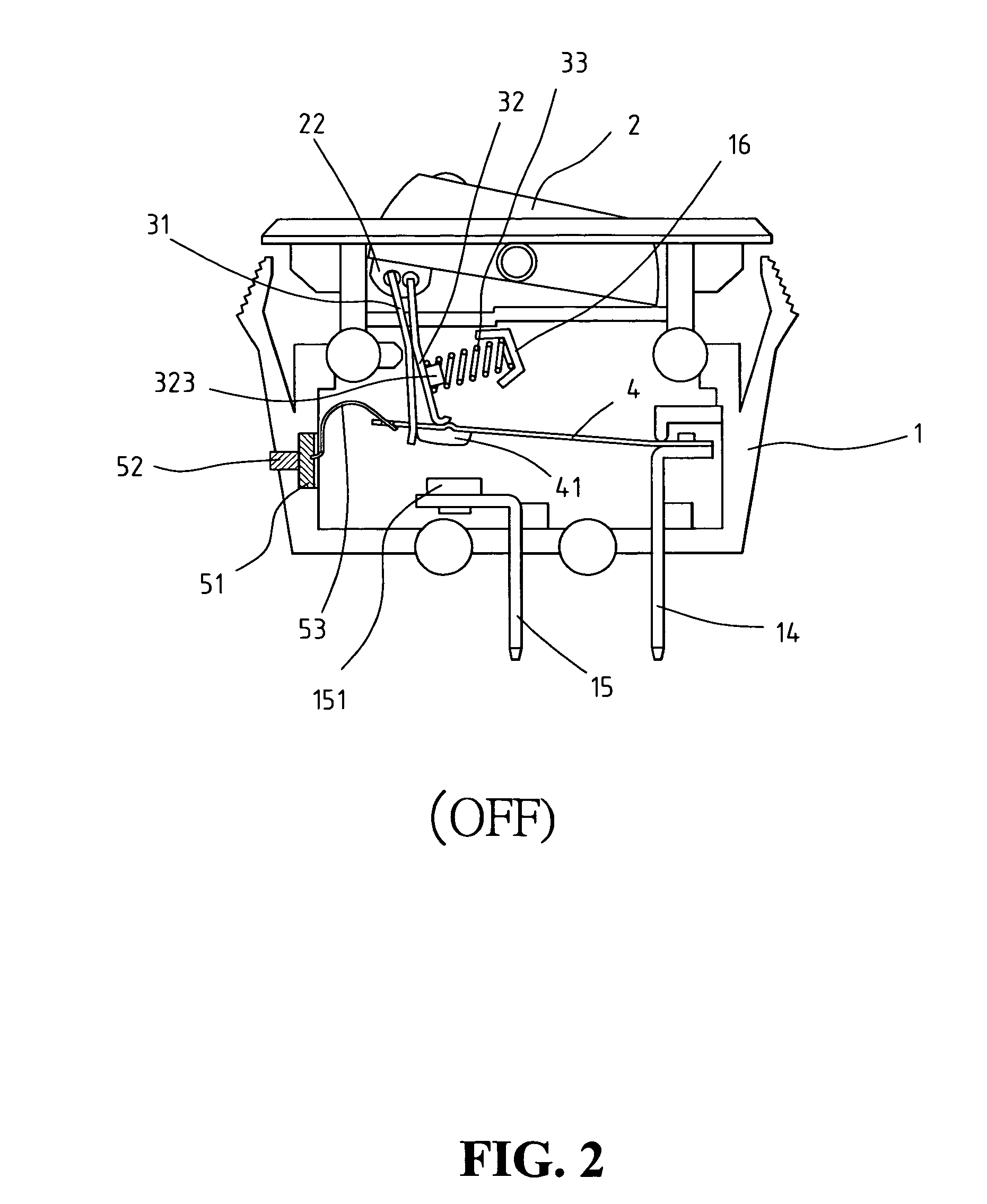
[0012]Referring to the drawings and in particular FIGS. 1 and 2, a safety switch device comprises a body 1 with a top opening 11 and two pivot holes 111 are defined through two opposite walls of the body 1. A switch member 2 is pivotably engaged with the top opening 11 of the body 1 by pivotally engaging two pivots 21 extending from two sides of the switch member 2 with the two pivot holes 111. A protrusion 22 extends from an underside of an end of the switch member 2 and includes two receiving holes 221, 222. Two slots 12, 13 are defined through an underside of the body 1 so that a first terminal 14 and a second terminal 15 extend through the two slots 12, 13. A first contact point 151 is connected to the second terminal 15 and a bi-metallic plate 4 has a first end fixed to a top of the first terminal 14 and a second contact point 41 connected to an underside of a second end of the bi-metallic plate 4. The second contact point 41 is located above the first contact point 151. A rece...


PUM


Abstract

A switch device includes a body with switch pivotably connected to a top thereof and two terminals extend through an underside of the body. A first contact point is connected to one of the terminals and a bi-metallic plate has a first end fixed to the other terminal. A second contact point is connected to an underside of a second end of the bi-metallic plate and located above the first contact point. A pull member has an upper end pivotably connected to the switch member and a lower end of the pull member supports the underside of the second end of the bi-metallic plate. An upper end of a push member is pivotably connected to the switch member and a lower end of the push member is in contact with the bi-metallic plate. A spring is biased between the push member and the body so as to provide a push force to the push member. A board movably received in a recess in an inside of the body and movable by an adjusting member extending through a hole through the body. A biasing member has a first end connected to the second end of the bi-metallic plate and a second end of the biasing member is engaged with the board. The biasing force of the biasing member relative to the bi-metallic plate is adjusted by moving the adjusting member.

Description

FIELD OF THE INVENTION[0001]The present invention relates to a safety switch including a adjusting assembly to adjustably keep proper flexibility of the bi-metallic plate to ensure that the bi-metallic plate is deformed as desired under overload conditions.BACKGROUND OF THE INVENTION[0002]A conventional switch device, especially for those switches using bi-metallic plate to prevent from being burn when an overload is happened, generally includes a bi-metallic plate which is deformed under overload conditions so as to separate the two contact points respectively located on the bi-metallic plate and one of the two terminals. Some inherent shortcomings for these conventional safety switch devices are found. There are too many parts involved in the safety switch device and a longer period of time is required when assembling the switch device, this increases the cost of the products. The parts might be arranged inaccurately and affects the deformation of the bi-metallic plate. Once the b...

Claims


Application Information

Patent Timeline
Patent Type & Authority Patents(United States)
IPC IPC(8): H01H37/70H01H37/18H01H37/52
CPCH01H71/7436H01H73/26
Inventor YU, TSUNG-MOU
Owner YU TSUNG MOU
Why Eureka
Try Eureka