Smoke detector

a smoke detector and detector technology, applied in the field of smoke detectors, can solve the problems of affecting the miniaturization affecting the safety of the smoke detector, and generating irregular noise light that cannot be sufficiently attenuated by the light trap, so as to save lives and property

Active Publication Date: 2007-07-24
LIXIL NITTAN
View PDF9 Cites 15 Cited by
  • Summary
  • Abstract
  • Description
  • Claims
  • Application Information

AI Technical Summary

Benefits of technology

[0007]It is therefore an object of the invention to provide a smoke detector which effectively suppresses incidence of noise light resulting from light emitted from a photo emitter to a light detecting region, to thus increase an S / N ratio by a large extent, thereby enabling significant reduction of false alarms attributed to the noise light.

Problems solved by technology

When such a smoke detector is adopted, noise light can be caused to enter the light trap, to thus attenuate the noise light.
Since light emitted from the photo emitter is reflected by edge sections of wall members constituting the labyrinth structure, irregular noise light of an amount that cannot be sufficiently attenuated by the light trap is generated.
Therefore, the noise light may enter the light detecting region, to thus cause a false alarm.
Accordingly, either case requires a large space for disposing the light trap, whereby miniaturization of the smoke detector has encountered difficulty.
In addition, the smoke detector disclosed in Japanese Patent Publication No. 2000-65741A includes another member such as a lens in addition to the light trap, whereby the cost for manufacturing the smoke detector may be increased.
Furthermore, the light trap and / or the lens may inhibit smoke from flowing into the dark chamber.

Method used


Image

  • Smoke detector
  • Smoke detector
  • Smoke detector

Examples


first embodiment

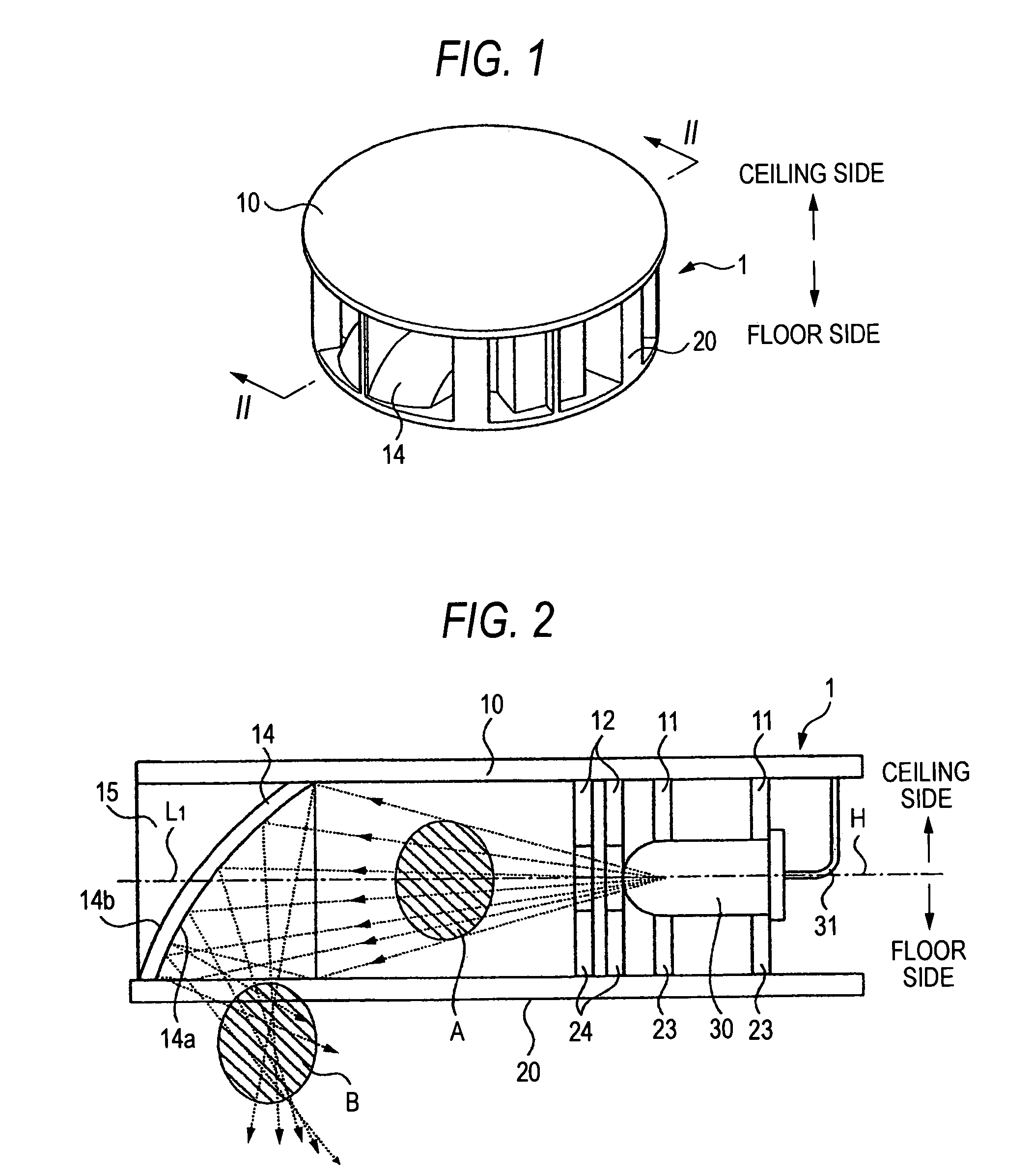
[0040]First, a smoke detector will be described by reference to FIGS. 1 to 8.

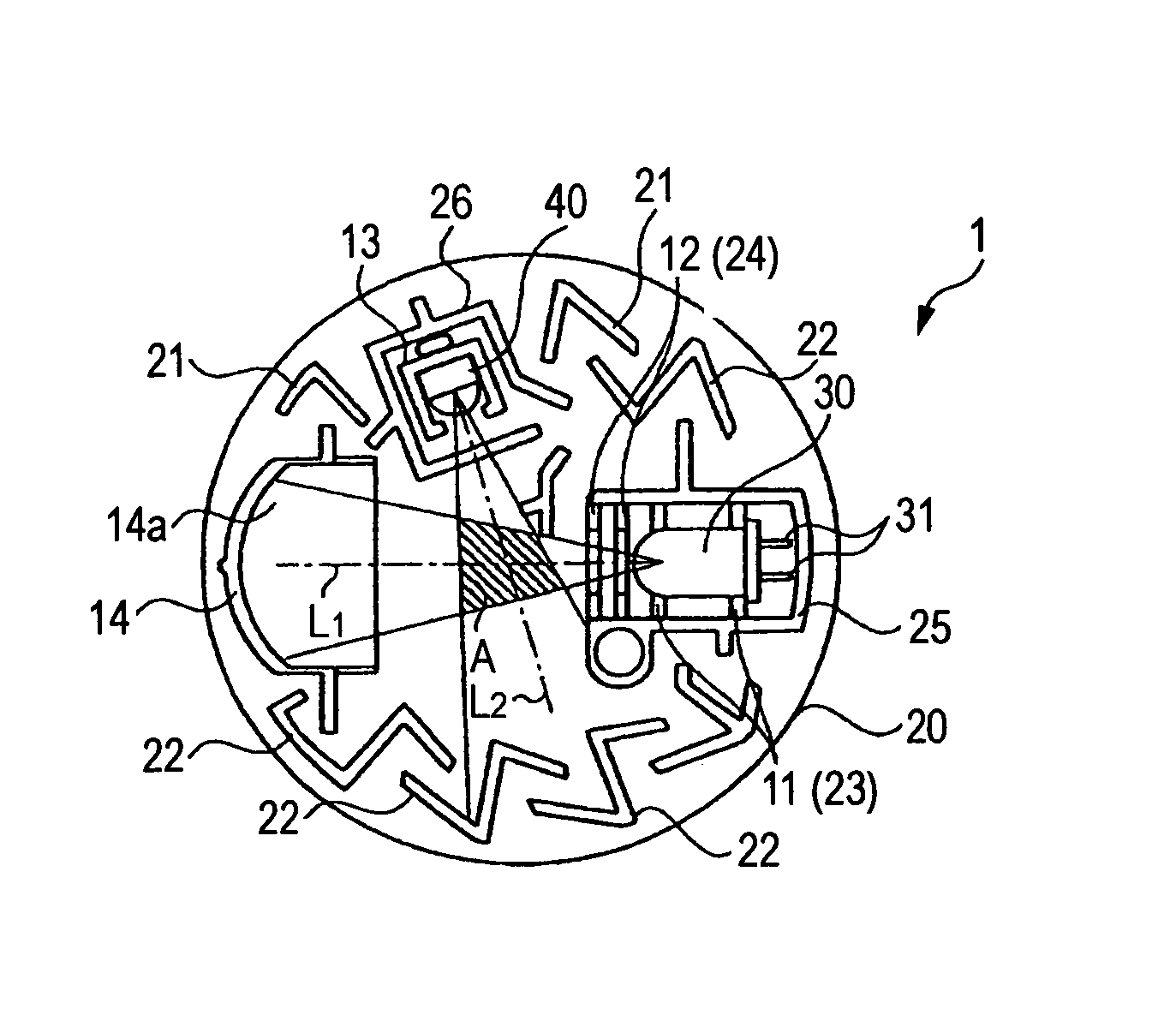
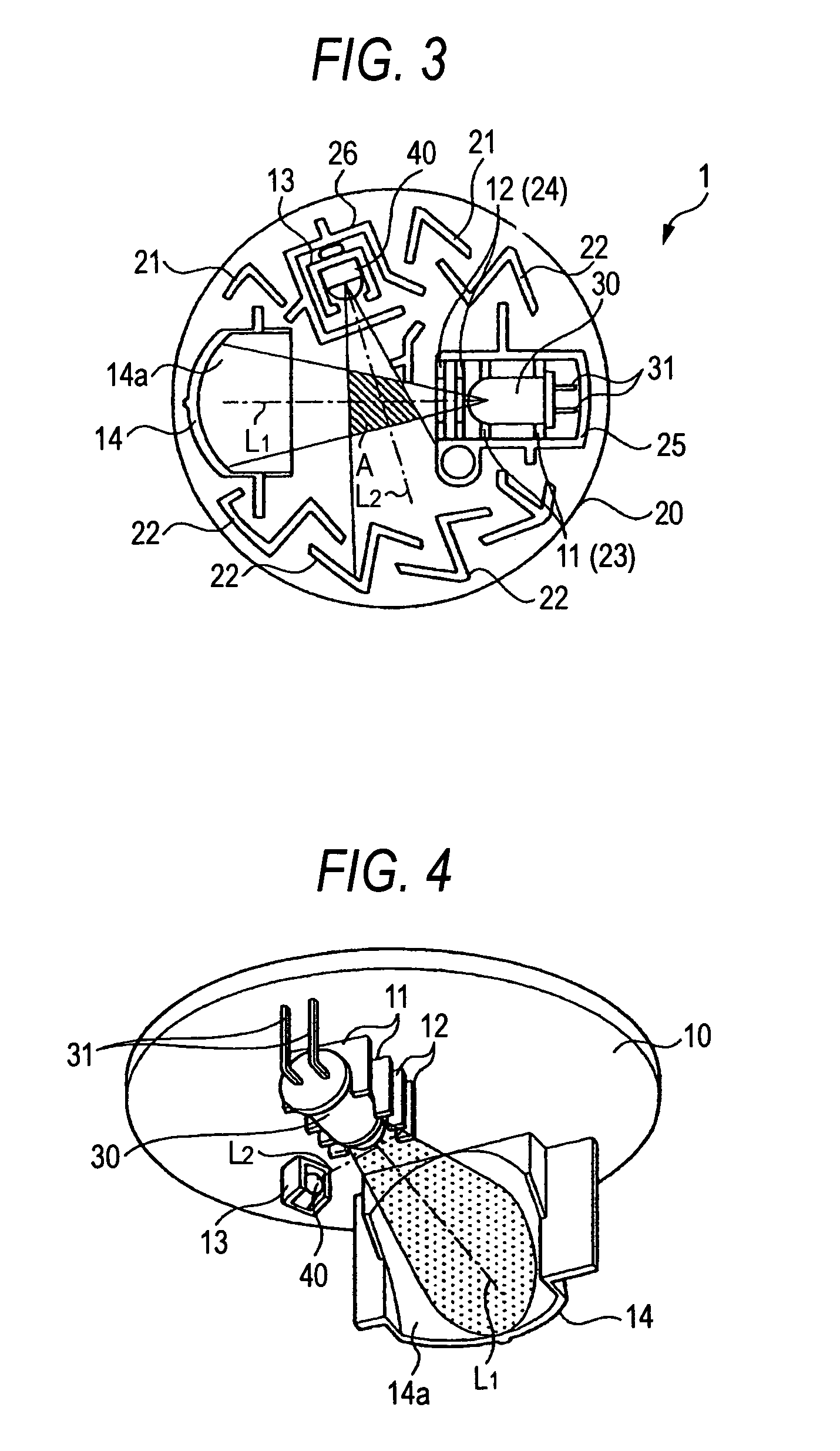
[0041]As shown in FIGS. 1 to 3, the smoke detector comprises a dark chamber 1 of a thick disk-shape constituted of an upper member 10 and a lower member 20; a photo emitter (light-emitting element) 30 and a photo detector (light-sensitive element) 40, both of which are disposed inside the dark chamber 1; an unillustrated circuit board for controlling the photo emitter 30 and the photo detector 40. The smoke detector is installed on a ceiling with the upper member 10 facing a ceiling and the lower member 20 facing a floor. The photo detector 40 receives scattered light in a predetermined smoke detecting region A (see FIGS. 2 and 3), whereby the smoke detector detects a fire.

[0042]As shown in FIGS. 1 and 4 to 6, the upper member 10 has a tabular member which is circular in a plan view, and a variety of members disposed on the lower face of the tabular member. The upper-member 10 and the lower member 20 const...

third embodiment

[0066]Alternatively, the following configuration can also be employed as the invention. A plurality of slits 29 are formed on the light-incidence face of the tabular member of the lower member 20 as shown in FIG. 10 in place of the saw-toothed section 28 shown in FIG. 9, thereby causing light to escape to the outside through the slits 29. The slits 29 in this case also serve as the attenuator.

[0067]In the above embodiments, the dark chamber 1 is of a thick disk-shaped and circular in plan view has been described. However, the shape of the dark chamber 1 is not limited thereto.

[0068]In the above embodiments, the reflective converger 14, the shielding wall 25, and the shielding wall 26 are rendered to be a portion of the labyrinth structure. However, the labyrinth structure may be constituted of the wall members 21 and the wall members 22; and the reflective converger 14, the shielding wall 25, and the shielding wall 26 may be disposed inside the labyrinth structure.


PUM

PropertyMeasurementUnit
angleaaaaaaaaaa
optical axisaaaaaaaaaa
structureaaaaaaaaaa

Abstract

A dark chamber is adapted to accommodate smoke particles. A photo emitter and a photo detector are disposed in the dark chamber. In a first region, a region where light emitted from the photo emitter passes and a region where the photo detector is capable of detecting light are overlapped, so that light emitted from the photo emitter and scattered by the smoke particles is detected by the photo detector. A photo converger converges light passed through the first region at a second region where is an outside of the first region.

Description

BACKGROUND OF THE INVENTION[0001]The present invention relates to a smoke detector.[0002]Smoke detectors for detecting smoke through detection of scattered light by smoke particles have conventionally been proposed and put into practice. Such a smoke detector detects a fire as follows. The smoke detector has a dark chamber for storing a photo emitter and a photo detector. Light emitted from the photo emitter is scattered by smoke particles having flowed into the dark chamber, to thus generate scattered light. The photo detector receives the scattered light.[0003]In recent years, smoke detectors including light traps for inhibiting noise light (light generated by reflection, by an inner wall of the dark chamber, of light having been emitted from the photo emitter) from reaching the photo detector are disclosed in, for example, Japanese Patent Publication Nos. 11-248628A, 2000-65740A and 2000-65741A. When such a smoke detector is adopted, noise light can be caused to enter the light t...

Claims


Application Information

Patent Timeline
Patent Type & Authority Patents(United States)
IPC IPC(8): G08B17/10G01N21/53G08B17/107
CPCG08B17/107G08B17/113G01N21/53
Inventor YAMASAKI, RYOICHIUENO, TAKESHIOYA, YASUNORI
Owner LIXIL NITTAN
Why Eureka
Try Eureka