
Static eliminator

a technology of static electricity and eliminator, which is applied in the direction of electrostatic charges, emergency protective arrangement details, electrical equipment, etc., can solve the problems of large installation space, spark discharge or short, and static electricity cannot be eliminated in the static generation area

Active Publication Date: 2007-07-24
TRINC
View PDF4 Cites 13 Cited by
  • Summary
  • Abstract
  • Description
  • Claims
  • Application Information

AI Technical Summary

Benefits of technology

"The patent describes different types of static eliminators that can be used to reduce static charge in various applications. The static eliminators include an ion generating portion in the form of a tape, a self-discharged static eliminator with conductors and discharge whiskers, and a DC type of fiber-like self-discharged static eliminator with plus and minus fiber electrodes. The invention also includes an insulation reserving means to prevent spark discharge or short due to access of electrodes. The technical effects of the invention include reducing static charge and improving the performance of various applications."

Problems solved by technology

Since the ion generation portion of the static eliminator of the former is shaped in the form of box or rod, a large space is required to install it.
Therefore, since the static eliminator can not be installed in the machine or in the narrow gap, the static electricity can not be eliminated in the area of static generation.
However, with the conventional DC type of fiber-like static eliminator as shown in FIG. 31 in which a multiplicity of fiber electrodes are disposed in parallel on support on its opposite sides, if the discharge electrodes project from the end of support, the leading ends of discharge electrodes approach to each other due to static force, which would result in the spark discharge or short.

Method used


Image

  • Static eliminator
  • Static eliminator
  • Static eliminator

Examples


first embodiment

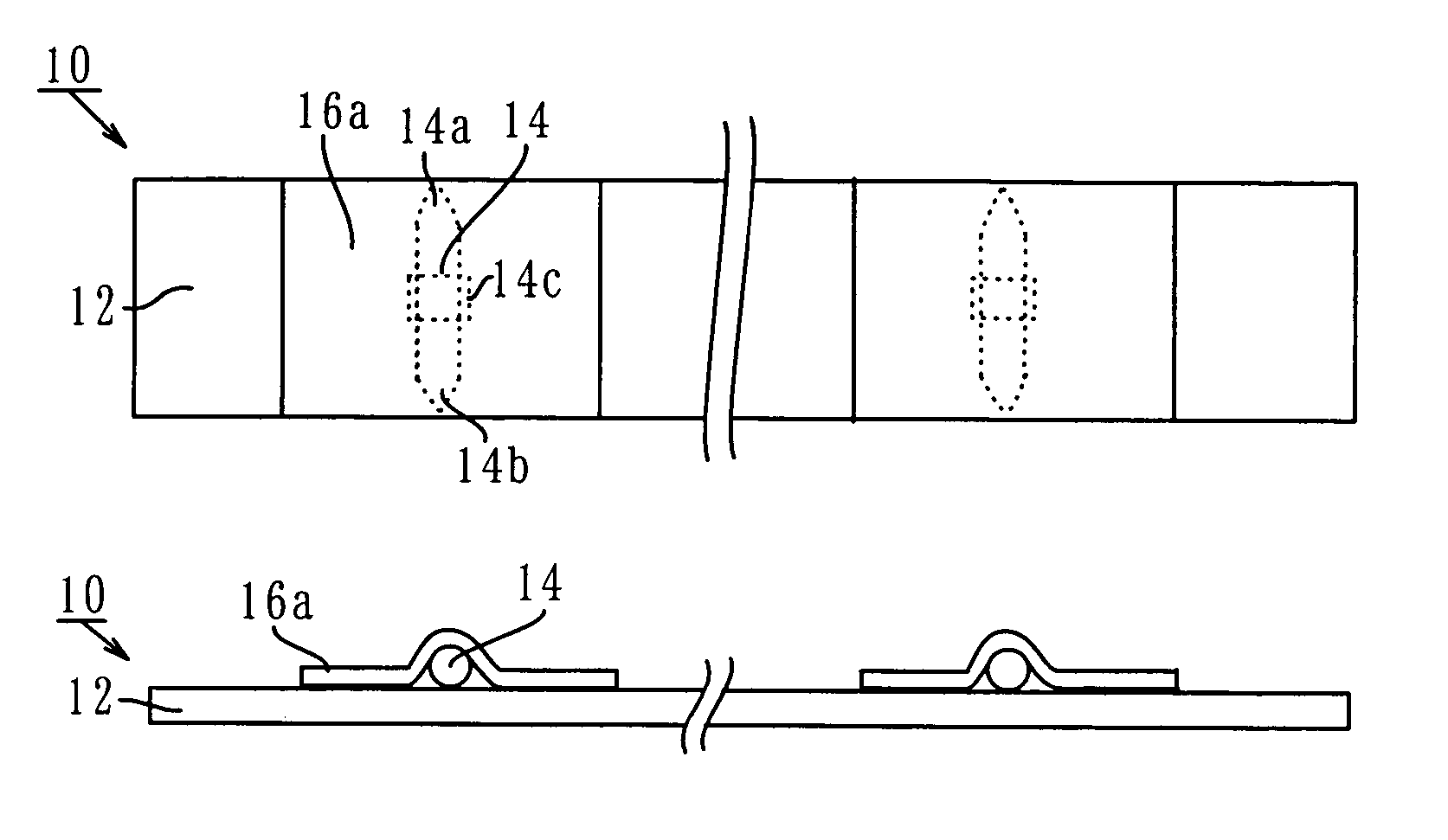
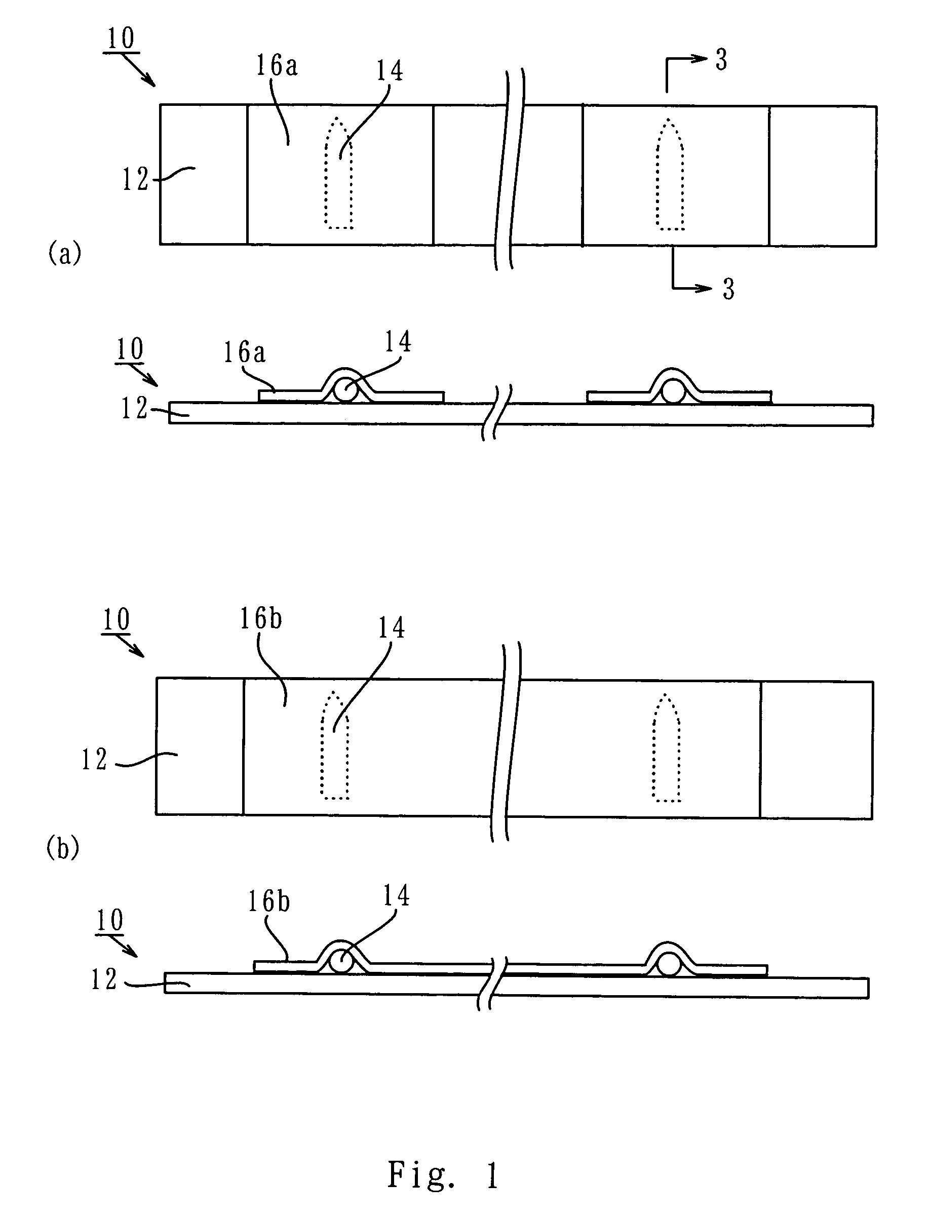
[0051]FIG. 1 shows a tape type of static eliminator in accordance with the first embodiment of the present invention. In FIG. 1 a tape-type static eliminator, specifically, a tape-type ion generator of the static eliminator 10 includes a plurality of discharge electrodes 14 for generating ions on a narrow thin board tape 12. Each discharge electrode 14 is disposed in parallel on the board tape 12 and the discharge end of each discharge electrode 14 is oriented in a direction to issue ions from one side of the board tape 12. Since the discharge electrodes are applied with high voltage such as above several kV, it is preferred that a plurality of short cover tapes 16a as shown in FIG. 1a or an elongated cover tape as shown in FIG. 1b are provided for covering over the discharge electrodes 14. The discharge electrodes 14 are is power supplied by conductor or electric supply line, not shown in FIG. 1, through a high voltage generating device, not shown, from a power supply, not shown.

[0...

second embodiment

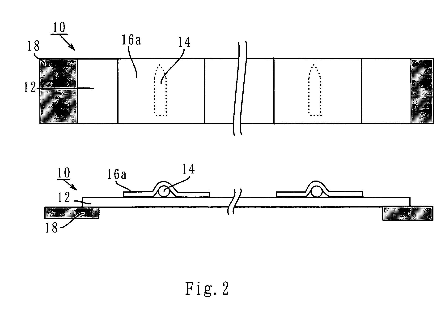
[0055]FIG. 2 shows a tape type of static eliminator in accordance with the second embodiment of the present invention. In case that the ion generating portion is in the form of tape and is flexible, the static eliminator can be suspended on opposite ends by pulling it. In such a case, only holders 18 provided on the opposite ends are required for pulling. Therefore, a support for supporting ion generating portion from its rear side is not necessary. Furthermore, the problem in that the support absorbs ions can be solved. Although the short cover tapes 16a is shown in FIG. 2, the elongated cover tape 16b may be used.

third embodiment

[0056]FIG. 3 shows a tape type of static eliminator in accordance with the third embodiment of the present invention. FIG. 3a and FIG. 3b are cross sectional views along lines 3—3 of FIG. 1. In FIG. 3a, conductors 20 and 22 are used for supplying electric power to discharge electrodes 14. The conductors 20 and 22 generate plus ions and minus ions, respectively, and power supply to each discharge electrode 14 is carried out by connecting its terminal and conductor 20 or 22. These conductors 20 and 22 are supplied with power from a high voltage generating device, not shown. In FIG. 3b, the board tape 12 itself is an electronic circuit board with an electronic circuit pattern which supplies power to the discharge electrodes. As a circuit pattern, portions 24a and 24b corresponding to the conductor or power supply line are provided. In this manner, in case that the electronic circuit pattern is provided, FPC or flexible print circuit, or FFC or flexible flat cable may be used.


PUM


Abstract

There is provided a static eliminator which comprises an ion generating portion in the form of tape. There is also provided a self-discharged static eliminator comprising an conductor provided with discharge whiskers in which the conductor is applied with a predetermined voltage. There is also provided a DC type of self-discharged fiber-like static eliminator which comprises plus fiber electrodes applied with plus voltage, minus fiber electrodes applied with minus voltage, a support disposed between the plus and minus electrodes for supporting the plus and minus electrodes and provided with insulation reserving member for preventing the spark discharge or short due to the access of the plus and minus electrodes.

Description

TECHNICAL FIELD [0001]This invention generally relates to a static eliminator, and more particularly, to a tape type of static eliminator and a self-discharged static eliminator.BACKGROUND OF INVENTION [0002]From the viewpoint of construction, the ion generating portion of the conventional static eliminators are shaped in the form of box or rod.[0003]From the viewpoint of discharge property, there is a self-discharged static eliminators. The self-discharged static eliminator uses conductive thin fibers. The discharge occurs from the leading ends of the fibers when the difference of static potential between the fibers and the object to be discharged or the fibers themselves rises above a certain value, which results in the cut-down of static electricity of the charged object. The self-discharged static eliminator is used to discharge static electricity of the charged objects by approaching the static eliminator to the charged objects. The operators in the factory wear the self-discha...

Claims


Application Information

Patent Timeline
Patent Type & Authority Patents(United States)
IPC IPC(8): H02H1/00H01T23/00H05F3/02
CPCH01T23/00B65H75/425B65H75/4457B65H2402/42B65H2403/70B65H2701/33
Inventor TAKAYANAGI, MAKOTO
Owner TRINC
Learn More