Wave gear device

a gear device and wave technology, applied in the direction of gears, belts/chains/gearrings, mechanical instruments, etc., can solve the problems of limited small flexural stress caused by thereby, and achieve the effect of reducing stress concentration and increasing maximum allowable transmission torqu

Active Publication Date: 2007-07-31
HARMONIC DRIVE SYST IND CO LTD
View PDF6 Cites 14 Cited by
  • Summary
  • Abstract
  • Description
  • Claims
  • Application Information

AI Technical Summary

Benefits of technology

[0013]It was recognized in the present invention that flexural stress acting on a diaphragm of a flexible external gear caused by elliptical deformation is extremely small compared to shear stress occurring due to torque transmission in a cup-shaped wave gear device having a high reduction ratio of 100 or higher, and a cross-sectional shape for the diaphragm was discovered that is suited for alleviating stress concentration primarily caused by shear stress and increasing a maximum allowable transmission torque.

Problems solved by technology

However, in the case of the wave gear device having a high reduction ratio of 100 or higher, since the amount of elliptical deformation is small, the flexural stress caused thereby is also small, and the shear stress caused by transmission torque takes precedence.
As a result, a maximum allowable transmission torque is limited since an excessive allowable flexural stress is employed and an allowable shear stress is kept low when the cross-sectional shape of the diaphragm of the wave gear device with the high reduction ratio is set.

Method used


Image

  • Wave gear device
  • Wave gear device
  • Wave gear device

Examples


Embodiment Construction

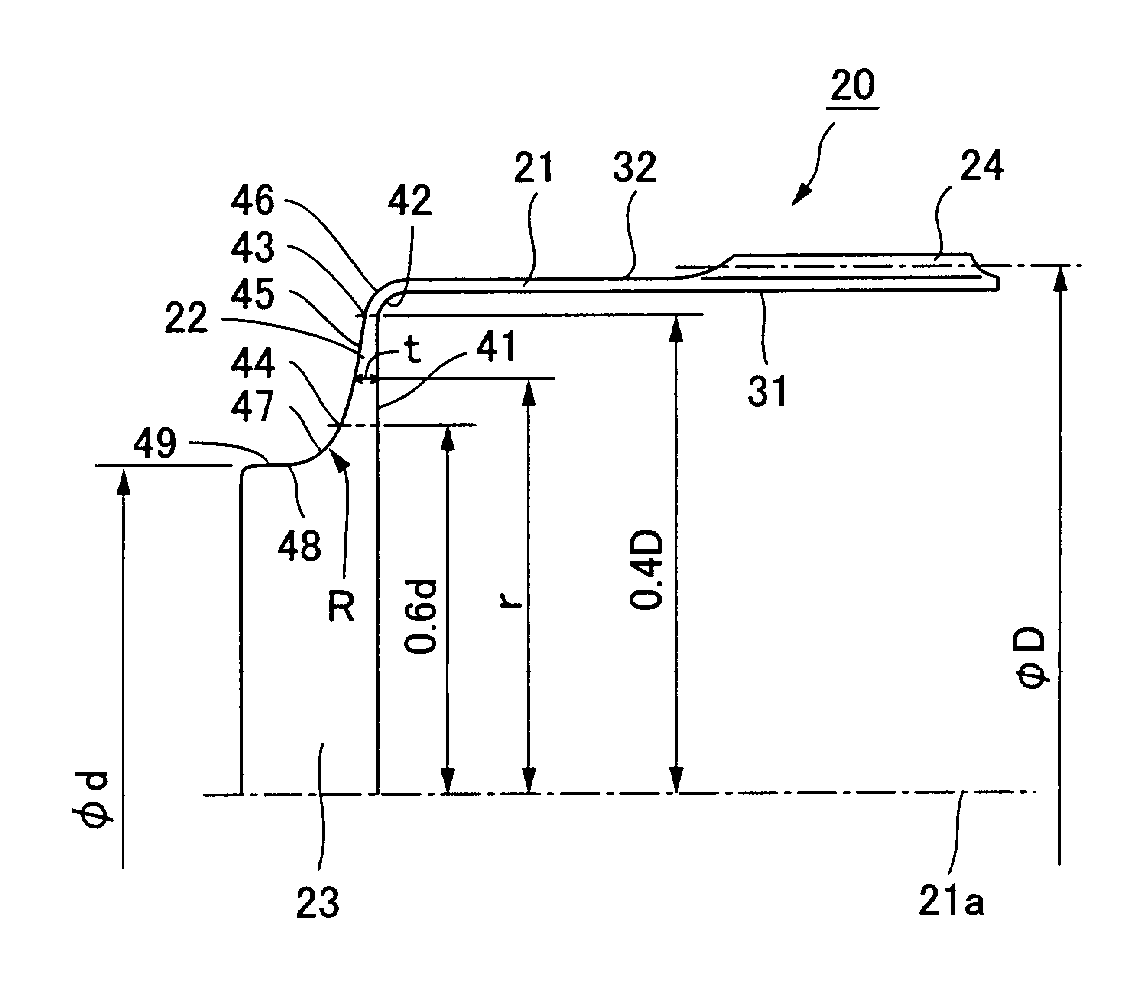
[0024]An example of a cup-shaped flexible external gear of a cup-shaped wave gear device according to the present invention will be described with reference to the drawings.

[0025]FIG. 4 is a longitudinal sectional view showing the cup-shaped flexible external gear of the present example. A flexible external gear 20 of the present example has the same basic shape as that of the prior art (see FIGS. 1 and 2), and is provided with a cylindrical body 21 that can be flexed in a radial direction, an annular diaphragm 22 extending towards inside in a radial direction from one end in the direction of a central axis 21a of the cylindrical body, a discoid rigid boss 23 integrally formed in concentric fashion in a center portion of the diaphragm 22, and external teeth 24 formed in an external peripheral surface portion of the other end of the cylindrical body 21.

[0026]Here, a thickness t is a value that satisfies the following conditional expression (1):

t=A / r2  (1)

[0027]where t is the thicknes...


PUM


Abstract

A diaphragm of a cup-shaped flexible external gear of a cup-shaped wave gear device having a high reduction ratio of 100 or higher is given a thickness t in a position of a radius r of the diaphragm whereby the thickness t is a value that satisfies the expression A / r2 when A is a constant. The constant A is preferably a value that satisfies the expression 0.0014 D3<A<0.0026 D3, where D is a pitch diameter of the flexible external gear, and the range of the radius r whereby the thickness t is defined as described above in the diaphragm is preferably set to satisfy the expression 0.6 d<r<0.4 D, where d is a diameter of a discoid rigid boss made continuous with an internal peripheral end of the diaphragm. Stress concentration can be alleviated, and it is possible for the allowable transmission torque to be increased compared to the prior art.

Description

BACKGROUND OF THE INVENTION[0001]1. Field of the Invention[0002]The present invention relates to a cup-shaped wave gear device having a high reduction ratio of 100 or higher, for example, and particularly relates to a wave gear device in which a diaphragm of a cup-shaped flexible external gear has a cross-sectional shape that is adapted for alleviating stress concentration.[0003]2. Description of the Related Art[0004]Known wave gear devices include a cup-shaped wave gear devices in which a flexible external gear thereof is cup-shaped. FIG. 1 is a longitudinal sectional view showing a typical cup-shaped wave gear device, and FIG. 2 is a block diagram showing the structure thereof in cross section in a plane perpendicular to a central axis of the device. As shown in these drawings, a cup-shaped wave gear device 1 is provided with an annular rigid internal gear 2, a cup-shaped flexible external gear 3 disposed in concentric fashion inside the internal gear, and an elliptically profiled...

Claims


Application Information

Patent Timeline
Patent Type & Authority Patents(United States)
IPC IPC(8): F16H33/00
CPCF16H49/001Y10T74/19F16H2049/003
Inventor KIYOSAWA, YOSHIHIDETAKIZAWA, NOBORU
Owner HARMONIC DRIVE SYST IND CO LTD
Why Eureka
Try Eureka